
Instruction manual


40
Power-OFF and magnetic contactor (MC)
3.3 Power-OFF and magnetic contactor (MC)
(1) Inverter input side magnetic contactor (MC)
On the inverter input side, it is recommended to provide an MC for the following purposes.
(Refer to page 4 for selection.)
1) To release the inverter from the power supply when the fault occurs or when the drive is not functioning (e.g. emergency
stop operation). For example, MC avoids overheat or burnout of the brake resistor when heat capacity of the resistor is
insufficient or brake regenerative transistor is damaged with short while connecting an optional brake resistor.
2) To prevent any accident due to an automatic restart at restoration of power after an inverter stop by a power failure
3) To separate the inverter from the power supply to ensure safe maintenance and inspection work.
The inverter's input side MC is used for the above purpose, select class JEM1038-AC3 MC for the inverter input side
current when making an emergency stop during normal operation.
(2) Handling of inverter output side magnetic contactor
Switch the magnetic contactor between the inverter and motor only when both the inverter and motor are at a stop. When the
magnetic contactor is turned ON while the inverter is operating, overcurrent protection of the inverter and such will activate.
When an MC is provided for switching to the commercial power supply, for example, switch it ON/OFF after the inverter and
motor have stopped.
REMARKS
Since repeated inrush currents at power ON will shorten the life of the converter circuit (switching life is about 1,000,000 times),
frequent starts and stops of the magnetic contactor must be avoided. Turn ON/OFF an input signal (forward/reverse rotation
command) via CC-Link communication to start/stop the inverter.
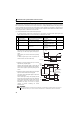
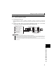
For the system, which requires a shutoff of the main power supply at an inverter failure, configure a sequence for the
programmable controller to monitor inverter failures and turn OFF the magnetic contactor at a failure via CC-Link
communication. (Use the Y91 signal to check the failure, which arises from a faulty inverter circuit or faulty connection. Refer to
page 170 for the details of the Y91 signal.)
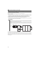
Output moduleCC-Link
master module
CPU module
U
V
W
R/L1
S/L2
T/L3
Motor
IM
Inverter
Y00
MC
Three-phase AC
power supply
MCCB MC
CC-Link
communication
connector
CC-Link
dedicated
cable
COM