
Instruction manual


62
Details of I/O signals
4.6.2 Details of remote registers
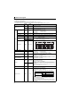
(1) Remote register (master module to inverter)
Remote register definition
∗1 When Pr. 37 is not equal to "0", this will be machine speed display (1 increments).
∗2 When Pr. 541 Frequency command sign selection (CC-Link) = "1", the setting value has either + or -. When the setting value is negative, the command is
inversed from starting command.
Setting range: -327.68Hz to 327.67Hz (-327.68 to 327.67) 0.01Hz increments.
For details refer to page 106.
∗3
When
Pr. 128
= "50, 51, 60, 61", they are valid. If the data outside the range is set, the previous setting is retained.
Refer to page 203 for details of Pr. 128.
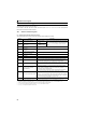
Device No. Signal Description
RWw0
Monitor code1/
Monitor code2
Set the monitor code to be monitored (Refer to page 66). By setting "1" in RYC after setting, the
specified monitored data is stored in RWr0/RWr1.
RWw1
Set frequency *1, *2
⋅ Specify the set frequency or machine speed. At this time, whether to write to RAM or
EEPROM is decided with the RYD and RYE settings. After setting the set frequency in this
register, set "1" in RYD or RYE to write the frequency. After writing of frequency is
completed, "1" is set in RXD or RXE in response to the input command.
⋅ The setting range is 0 to 400.00Hz (0.01Hz increments). Write "40000" when setting
400.00Hz.
RWw2
Link parameter extended
setting/Instruction code
Set the instruction code for execution of operation mode rewrite, parameter read/write, error
reference, error clear, etc. (Refer to page 64) Set "1" in RYF to execute the corresponding
instruction after completing the register setting. "1" is set in RXF after completing the
execution of the instruction.
When a value other than "0" is set in Pr. 544 CC-Link extended setting, upper 8 bits are link
parameter extended setting.
Example) When reading Pr. 160, instruction code is H0200.
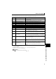
RWw3
Write data
Set the data specified by the RWw2 instruction code. (When required)
Set "1" in RYF after setting RWw2 and this register.
Set zero when the write code is not required.
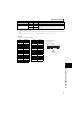
RWw4
Monitor code 3
Set the monitor code to be monitored. By setting "1" in RYC after setting, the specified
monitored data is stored in RWr.
( indicates a register number. (RWr4 to 7))
RWw5
Monitor code 4
RWw6 Monitor code 5
RWw7
Monitor code 6
RWw8
Faults history No.
Set the individual fault number of the faults history that you want to read. Up to the 8th
previous fault can be read.
Last two digits: H00 (latest fault) to H07 (8th oldest fault)
When H08 to HFF are set, fault record becomes an unfixed value.
RWw9
PID set point *3
Set the PID set point
Setting range : "0 to 100.00%"
⋅ Input a value 100 times greater than the value to be
set.
For example, input "10000" when setting 100.00%.
⋅ Refer to page 203 for details of PID control.
RWwA
PID measured value *3
Set the PID measured value
Setting range : "0 to 100.00%"
RWwB
PID deviation *3
Set the PID deviation.
Setting range : "-100.00% to
100.00%"
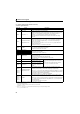
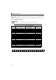
RWw10,
RWw12,
RWw14,
RWw16,
RWw18
Link parameter extended
setting/Instruction code
Set the instruction code (refer to page 64) for execution of operation mode rewrite,
parameter read/write, error reference, error clear, etc. The instructions are executed in
the following order by setting "1" in RYF after completing the register setting:
RWw2, 10, 12, 14, 16, then 18. After completing the execution up to RWw18, "1" is set in
RXF. Set HFFFF to disable an instruction by RWw10 to 18. (RWw2 is always executed.)
The first 8 bits are link parameter extended setting.
Example) When reading Pr. 160, instruction code is H0200.
RWw11,
RWw13,
RWw15,
RWw17,
RWw19
Write data
Set the data specified by the instruction code of RWw10, 12, 14, 16, and 18. (when
required)
RWw10 and 11, 12 and 13, 14 and 15, 16 and 17, and 18 and 19 correspond each other.
Set "1" in RYF after setting the instruction codes (RWw10, 12, 14, 16, and 18) and the
corresponding register.
Set "0" when the write code is not required.