INVERTER FR-A800/F800 Safety Stop Function Instruction Manual CONTENTS 1. GENERAL DESCRIPTION ............................................ 2 2. INSTALLATION AND WIRING...................................... 3 3. EXAMPLE OF SAFETY SYSTEM CONFIGURATION .... 7 4. TEST AND CHECKING FAILURE ............................... 10 5. SAFETY PARAMETERS OF FR-A800/F800 ................
Compliance with the EU Machinery Directive – Functional Safety WARNING Any misuse of safety function could lead to personal injury or death, property damage, or economic loss. To ensure that the system complies fully with requirement of safety, make a system-level risk assessment. Mitsubishi Electric Co. cannot assume responsibility for any system to comply with safety directive. CAUTION The information of this manual is merely a guide for proper installation. Mitsubishi Electric Co.
1 GENERAL DESCRIPTION Features Mitsubishi FR-A800/F800 safety stop function prevents a drive from supplying rotational energy to motors. Dual safety channels ‘S1’ and ‘S2’ cut off the gate-drive power for IGBT to turn off. FR-A800/F800 SO R/L1 S/L2 T/L3 Logic SOC IGBTs +24V PC Fuse CPU RESET ASIC Gate Driver Gate Driver 24VDC S2 G G S1 Emergency stop button SIC SD Safety relay module / Safety programmable controller U V W M Fig.
2 INSTALLATION AND WIRING CAUTION The following information is merely a guide for proper installation. Mitsubishi Electric Co. cannot assume responsibility for the compliance or the noncompliance to any code, national, local or otherwise for the proper installation of this equipment. A hazard of personal injury and/or equipment damage exists if codes are ignored during installation.
CAUTION In order to meet safety stop, an approved safety relay unit to ISO13849-1 safety category 3 or better shall be used in conjunction with FR-A800/F800 as shown in example. In addition, all other components with in the safety stop loop shall be ‘safety approved’ types. WARNING To avoid an electric shock hazard, insert the magnetic contactor (MC) between power source and drive.
Table.3 Truth table of safety related signals Internal safety circuit status Input power OFF ON Input terminal , S1 S2 Output terminal Inverter running status SO Operation panel indication E.
●Wire and ferrule specification Table.4 Wire and ferrule specification Wire size (mm2) Ferrule with insulation collar 0.3 / 0.5 AI 0,5-10WH 0.75 AI 0,75-10GY 1 AI 1-10RD 1.25 / 1.5 AI1,5-10BK 0.75 (combined 2 wire) AI TWIN 2 X 0,75-10GY Crimping tool name CRIMPFOX 6 Ferrules and tools are distributed by Phoenix Contact. ●Jumper cable The jumper cable between S1,S2 and PC terminal between SIC and SD terminal has been installed in the factory as shown in Fig.2.
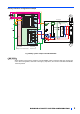
3 EXAMPLE OF SAFETY SYSTEM CONFIGURATION ●FR-A800/F800 configuration example R/L1 S/L2 T/L3 SO Logic SOC RESET START STF STOP STOP S2 Emergency stop button CPU ASIC Gate Driver Gate Driver 24V DC +24V X0 COM0 X1 COM1 XS0 XS1 IGBTs Z00 Z10 Z20 S1 Internal Safety Circuit 24V DC K1 G K2 24G G SIC SD Z01 Z11 Z21 +24V Safety relay module MELSEC QS90SR2SN-Q Fuse PC*1 FR-A800/F800 U V W M If the control logic is SINK logic, the common terminal is terminal SD. Fig.
●Multiple inverter configuration example R/L1 S/L2 T/L3 SO Logic SOC RESET S2 Emergency stop button CPU ASIC 24V DC +24V X0 COM0 X1 COM1 XS0 XS1 Gate Driver Gate Driver IGBTs Z00 Z10 Z20 S1 Internal Safety Circuit 24V DC K1 G G SIC K2 SD +24V Fuse 24G Z01 Z11 Z21 PC Safety relay module MELSEC QS90SR2SN-Q FR-A800/F800 U V W M R/L1 S/L2 T/L3 SO Logic SOC S2 CPU ASIC Gate Driver Gate Driver IGBTs S1 G G SIC SD +24V Fuse PC FR-A800/F800 U V W M Fig.
●Safety controller configuration example WS0 -CPU0 WS0-CPU0 WS0 -XTIO WS0-XTIO FLEXBUS+ FLEXBUS+ 24V 24V I1 I1 I2 I2 I3 I3 I4 I4 X1 Application Emergency stop button I5 I5 I6 I6 RESET 0V 0V I7 I7 I8 I8 FR-A800/F800 X2 SO R/L1 S/L2 T/L3 Logic SOC A1(24V) FLEXBUS+ FLEXBUS+ A1(24V) Q1 A2(0V) Application Q2 Q3 IGBTs +24V 24VDC PC Fuse CPU S2 ASIC Gate Driver G Gate Driver G S1 SIC Q4 SD A2(0V) U V W M MITSUBISHI safety controller MELSEC-WS series CPU module WS0-CPU0 Saf
4 TEST AND CHECKING FAILURE CAUTION To avoid systematic faults, a test even for faulty demands of the safety function has to be performed in order to check the correct function of the monitor signal. This test shall be carried out at system installation, any software changes, parameterization changes, and/or at least once per year. I/O status and failure FR-A800/F800 safety related I/O status obeys the following truth table. Table.
Diagnostic If the failure detected, FR-A800/F800 output alarm signal and indicate ‘E.SAF’ at the display. In case of FR-A800/F800 output the alarm, please take following action. 1) Check the S1-SIC and S2-SIC input signal logic is the same. If these are different logic, collect the input signal and reset the FR-A800/F800. 2) Disconnect the wire from S1, S2, SIC terminal, then reset or power-off and on. If the ‘SA’ letter is flashed up at display, there is failure in system except FR-A800/F800.
REVISIONS Print Date Manual Number Apr. 2013 BCN-A23228-001(E) Jun. 2013 BCN-A23228-001-A(E) Jul.
HEADQUARTERS EUROPEAN REPRESENTATIVES EUROPEAN REPRESENTATIVES EUROPEAN REPRESENTATIVES MITSUBISHI ELECTRIC EUROPE EUROPE B.V. German Branch Gothaer Straße 8 D-40880 Ratingen Phone: +49 (0) 21 02 / 486-0 Hotline: +49 2102 1805 000-765 /-766 Fax: +49 (0) 21 02 / 4 86-1 12 0 e mail: megfa-mail@meg.mee.com www.mitsubishi-automation.com GEVA AUSTRIA Wiener Straße 89 A-2500 Baden Phone: +43 (0) 2252 / 85 55 20 Fax: +43 (0) 2252 / 488 60 e mail: office@geva.co.at MITSUBISHI ELECTRIC IRELAND EUROPE B.V.