INVERTERS DRIVE SYSTEMS Quick start and reference guide Installation /// Wiring /// Settings /// Basic parameters /// Simple error codes /// Regular maintenance ///
Quick start guide /// Quick start guide /// Quick start guide /// Drives to rely on As a major global supplier of inverters, Mitsubishi has a reputation for using leading technology to produce the most reliable products. Did you know: Mitsubishi is the largest volume producer of inverters in the world. IMS, the International market research company, has voted Mitsubishi’s inverters most reliable in the past years. Mitsubishi invests over 6 % of its turnover in research and development. www.
Quick start guide /// Quick start guide /// Quick start guide /// Contents Getting started Know your inverter Mitsubishi inverter ranges Programming panels Inverter programming panels Installation and mounting General precautions Wiring Good earthing practice 4 5 5/6 7 7/8 9 9/10 11 11/12 Basic operation 13 Setting a frequency 13 Setting a parameter 14 Monitoring operation 15 Basic parameters 16/17 Common error codes 18/19 Regular maintenance 20 Common installation problems 21 My drive se
Getting started /// Getting started /// Getting started /// Know Start-up route map Start Installation and mounting Set basic parameters Wiring of the power supply and motor Starting the inverter End REGULAR MAINTENANCE Once the Inverter has been set-up and commissioned a series of regular maintenance checks should be performed to monitor the Inverter and motor performance is still at an optimum. 4 www.mitsubishi-automation.
w your inverter /// Know your inverter /// Know your inverter Mitsubishi Inverter Ranges FR-D700 Aluminium heat sink MITSUBISHI Quick setting control dial Programming and operation display – 7 segment Main body of Inverter Removable front cover Network connection is located underneath front cover Power input and motor wiring point FR-E700 Standard display Aluminium heat sink MITSUBISHI Main body of Inverter Option and network boards are fitted underneath front cover Removable front cover Power in
Know your inverter /// Know your inverter /// Know your in FR-F700 FR-A700 Hz A V Replaceable fan MON P.RUN PU EXT NET FWD REV PU EXT REV FWD MODE SET STOP RESET Programming and operation display – 7 segment FR-DU07 MITSUBISHI FREQROLF- 700 Aluminium heat sink ! Main body of Inverter ! and electric shock DANGER: Risk of injuryfollow the safety instructions before use. Read the manual and removing this cover.
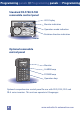
nverter /// Programming panels /// Programming panels /// Control Panels FR-D700/E700 embedded control panel FR-F700/A700 removable control panel FR-DU07 Using the digital dial The digital setting dial allows quick and easy selection of parameters and the setting of parameter values. The digital setting dial performs the function of the traditional keys as found on the FR-PU04 and FR-PU07 etc. All other buttons operate in a similar way to those found on traditional control units.
Programming panels /// Programming panels /// Programming Standard FR-F700/A700 removable control panel LED-Display Monitor indication Operation mode indication Rotation direction indication FR-DU07 Optional removable control panel MITSUBISHI FR-PU07 PARAMETER UNIT 50 0 0 Hz - - - STOP EXT POWER MON EXT FUNC SHIFT ESC 7 8 9 4 5 1 2 0 READ Monitor ALARM PrSET 6 PU ALARM lamp POWER lamp FWD 3 REV WRITE STOP RESET Operation keys FR-PU07 Optional comprehensive control panel for use
g /// Installation and mounting /// Installation and mounting /// General Precautions A major component of an Inverter’s design is a capacitor bank. The capacitors used can hold their charge for up to 15 minutes after power down. For your own protection from electrical shock please wait at least 15 minutes before checking the residual voltage level by placing a meter between terminals P/+ and N/- (resp. + and - for FR-D700 series). The voltage measured should not be more than 30 V DC.
Installation and mounting /// Installation and mounting /// Avoid installing the inverter in places where it will be exposed to direct sunlight, high temperatures or high humidity/moisture Ambient temperature -10 °C to +50 °C, 14 °F to 122 °F (non freezing) see note 1 Ambient humidity 90 % RH or less (non condensating) Storage temperature -20 °C to +65 °C (-4 °F to 149 °F) for short time e.g.
Wiring /// Wiring /// Wiring /// Wiring /// Wiring /// Wiring /// General Wiring All electrical products have to comply with European EMC regulations, but an important part of keeping that compliance is to use good wiring practice. The wiring schematics used in this section are shown demonstrating some of these practises, i.e the use of good earthing, and where required the use of filters.
Wiring /// Wiring /// Wiring /// Wiring /// Wiring /// Wiring // Good earthing practice From both LVD and EMC and a safety point of view it is essential that earthing connections are always made in the most thorough way possible. See below for examples of good EMC grounding.
// Basic operation /// Basic operation /// Basic operation /// Note regarding symbols used When a value or parameter needs to be set, the following symbol has been used. For inverters without a digital setting dial, the value should be set using their keys. Setting a frequency 1. Press the to put the inverter into PU operation – this is indicated by the PU LED being lit e.g. 2. Adjust the frequency value with the setting dial/keys. When the desired value is found press .
Basic operation /// Basic operation /// Basic operation /// Basic op 6.2 Setting a parameter 1. Ensure step #1 is completed as before. 2. Press the key to put the inverter into parameter mode – the display will change like this 3. Select the desired parameter with the setting dial/keys. When the desired parameter is found press the the current value for the selected parameter, e.g. key to see To adjust the setting, move the setting dial/keys required value. To set the value, press the , key, e.g.
peration /// Basic operation /// Basic operation /// Basic operation 6.3 Monitoring operation 1. Ensure step #1 is completed. 2. Press the key, current being drawn by the motor in Amps and present voltage level in Volts, e.g.
Basic parameters /// Basic parameters /// Basic parameters // Each inverter has a wide range of parameters that can be set to tune the inverter-motor system to the very best performance necessary, but to get an inverter working and to check it is installed correctly etc. you only need a handful of parameters.
// Basic parameters /// Basic parameters /// Basic parameters Basic parameters for FR-F700 and FR-A700 Parameter Factory setting Description 0 6/4/3/2/ 1.
Common error codes /// Common error codes /// Common err Model Error code FR-D700, FR-E700, FR-F700, FR-A700 E.OC[] Error A) The output current of the inverter has reached or exceeded 200 % of the rated current. B) The temperature of the main circuits of the inverter rises rapidly. Remedy Look for one of the following faults: A) A short circuit or ground fault across the main outputs. B) An excessive moment of inertia from the Load. C) Acceleration or deceleration times are too short.
ror codes /// Common error codes /// Common error codes /// Model Error code FR-D700, FR-E700, FR-F700, FR-A700 E.THM Error The electronic motor protection switch continually detects the motor current and the output frequency of the inverter. If a self-cooling motor operates over a long period at low speed but high torque, the motor is thermally overloaded and the protective function is activated. If several motors are operated by one inverter, use independent motor thermal protection.
Maintenance /// Maintenance /// Maintenance /// Maintenance /// C An inverter is a static unit mainly consisting of semiconductor devices processing high voltages and currents. Daily inspection should be performed to prevent faults from occuring due to adverse effects of the operating environment and to monitor the service life of the inverter. Other specific inspections should be carried out periodically.
Common problems /// Common problems /// Common problems Don’t guess! If you do not know or you are not sure check the manual or ask! Get the right voltage! Always check the voltage requirements of the inverter before wiring it to the supply. A simple check of the model name will identify the required input voltage. 40 = 400 V, three phase ... e.g. FR-F740 20S = 200 V, single phase ... e.g.
My drive settings /// My drive settings /// My drive settings // Mitsubishi Electric makes all possible efforts to provide only the highest quality automation products, meeting appropriate European legislation and requirements for Safety, EMC and hazardous materials etc. Before using any Mitsubishi automation product, installers and users should read the appropriate related installation, hardware, users and operation manuals where available.
// Quick start guide /// Quick start guide /// Quick start guide A world of automation solutions Robots Motion control and servos LV circuit protection Inverters Laser machines CNC controllers HMI and GOTs Micro PLCs EDM machines Modular PLCs Mitsubishi offer a wide range of automation equipment from PLCs and HMIs to CNC and EDM machines. A name to trust Since its beginnings in 1870, some 45 companies use the Mitsubishi name, covering a spectrum of finance, commerce and industry.
Global Partner. Local Friend. Mitsubishi Electric Europe B.V. /// FA - European Business Group /// Gothaer Strasse 8 /// D-40880 Ratingen /// Germany /// Tel.: +49 (0) 2102-4860 /// Fax: +49 (0) 2102-4861120 /// info@mitsubishi-automation.com /// www.mitsubishi-automation.com /// All trademarks and copyrights acknowledged. /// Specifications subject to change /// Art. no. 192913-C /// 08.