
Specifications


C-22
5.
Examples of Applications Using Various
Input and Output Terminals
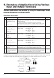
Various applications are possible by using the input/output termi-
nals and connectors as shown below.
Input/Output Specifications
1
2
3
4
5
6
Ter minal
External control input
terminal block for
start/stop the Lossnay
unit
(
TM2 123
)
Lossnay operation moni-
tor output terminal block
Output delay function 1
(
TM4 90
)
Lossnay malfunction
monitor output terminal
block
(
TM3 78
)
By-pass monitor output
terminal block
Output delay function 2
(
TM3 67
)
External control input
connector for By-pass
(
CN 16
)
External control input
connector for fan speed
(CN 16)
Specification
TM2 is the input terminal block for start/stop the Lossnay unit using external
equipment, such as a Mr. Slim
(
A-control
)
indoor unit or the BMS
(
Building
Management System
)
.
Use voltage
(
12V-24V DC
)
or uncharged a-contact for signal input.
(
Both voltage and no-voltage signals are compatible with pulse input; a pulse
signal duration of 200 ms or more is needed. Set DIP switch 2-2 to ON.
)
Output terminal during Lossnay unit operation.
(
uncharged a-contact signal output
.)
Output delay function 1 is possible by DIP switch 2-8
Contactor rating: Max 240V AC, 2A
24V DC, 2A
Min 220V AC, 100mA
5V DC, 100mA
Output terminal during Lossnay unit malfunction.
(
uncharged a-contact signal output.
)
Contactor rating: Max 240V AC, 1A
24V DC, 1A
Min 220V AC, 100mA
5V DC, 100mA
Output terminal during Lossnay unit malfunction.
(
uncharged a-contact signal output.
)
Output delay function 2 is possible by DIP switch 5-6
Contactor rating: Max 240V AC, 1A
24V DC, 1A
Min 220V AC, 100mA
5V DC, 100mA
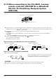
Input connector for switching By-pass.
Establish the wire connection by inserting the optional remote display adaptor
(PAC-SA88HA-E) in the connector CN16 (Ventilation mode selector).
Input connector for switching Hight/Low/Extra-Low fan speed.
Using marketed CO
2 sensor, etc., make connection by inserting the optional
remote display adaptor (PAC-SA88HA-E) in the connector CN16.
Page
C-26/C-27
C-28/C-73
C-26/C-27
C-70/C-74
C-26/C-27
C-26/C-27
C-28/C-29
C-28/C-70
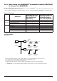
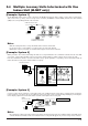
Lossnay Main/Sub Setting
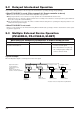
If multiple Lossnay system begin operation by one signal from an indoor unit of air conditioner or the like, make sure the unit
connected to the signal cable from the indoor unit of air conditioner is set to “Main,” and all the others are set to “Sub.”
Lossnay
(Main)
Remote controller
(PZ-60DR-E or PZ-41SLB-E)
Power
supply
External
device
Operating switch
for external device
Lossnay (Sub)
MAX 15 units
Power
supply
Lossnay (Sub)
Power
supply
Power
supply
Connect to
remote
controller
(PZ-60DR-E)
Connect
to third
Lossnay
Main/Sub selection
switch
(SW1)
Main Sub
21
21
Transmission cable
First Lossnay
Second
Lossnay
TM4
(Factory setting: main)
TM4
or
or
C-70
C-75