
Specifications
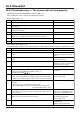
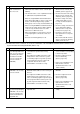

C-47
Do the signal cables meet regulations? (Type, diameter)
Checkpoint
1
No.
2Is the signal cable wired at least 5 cm away from the power supply cable?
3 Are multiple transmission or signal cables wired to the same power cable
duct?
4 Are multiple signal cables wired with multi core cables?
5Are the signal cables securely connected to the terminals?
6 Are the signal cables connected to the specified terminal blocks?
Operation monitor, operation monitor with delay function 1 : TM4 9, 0
Malfunction monitor : TM3 7, 8
Bypass operation monitor, operation monitor with delay function 2
: TM3 6, 7
7 Are the output capacities of the operation monitor, malfunction monitor, and
bypass operation monitor within the ratings?
Action
Use specified cables.
Wire the signal cable at least 5 cm
away from the power supply cable.
Wire the transmission cables away
from the signal cables.
Using suitable cables, wire the sig-
nal cables so that they are separat-
ed from one another.
Connect them securely.
Connect them to the specified termi-
nal blocks.
Use within the ratings.
Signal cables to external devices (Table 1-1-4)
Check the following checkpoints when outputting the operation monitor, air supply fan operation monitor, mal-
function monitor, bypass operation monitor, and operation monitor with delay function.
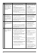
8 When using the operation monitor, is the setting of the output signal cor-
rect?
<When using PZ-60DR-E>
Check the operation monitor setting
from the function selection.
(Refer to page C-70)
<When not using PZ-60DR-E>
Check the setting of the operation
monitor (SW5-2) on the Lossnay cir-
cuit board. (Refer to page C-74)
9 When using the operation monitor with delay function, is the setting of the
output signal correct?
Check the settings of the TM4 9,
0 output setting (SW2-8), and the
TM3 6, 7 output setting (SW5-6)
on the Lossnay circuit board.
(Refer to page C-74 and C-75)
10 When PZ-60DR-E is not used, are the function selection switches (SW2,
SW5) on the Lossnay circuit board set correctly?
Set the switches correctly to corre-
spond with the application.
(Refer to page C-72)
11 When PZ-60DR-E is used, is the function selection set correctly? Set it correctly to correspond with
the application.
(Refer to page C-78 to C-90)
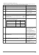
Output Maximum rating Minimum rating
Operation monitor
Operation monitor with delay function 1
240 V AC 2 A
24 V DC 2 A
220 V AC 100 mA
5 V DC 100 mA
Malfunction monitor 240 V AC 1 A
24 V DC 1 A
220 V AC 100 mA
5 V DC 100 mA
Bypass operation monitor
Operation monitor with delay function 2
240 V AC 1 A
24 V DC 1 A
220 V AC 100 mA
5 V DC 100 mA