FLOOR AND CEILING TYPE AIR CONDITIONERS No. OB239 SERVICE MANUAL Wireless type Model MCF-13NV- E3 (WH) ·MUCF-13NV- E3 (When installed on the floor) CONTENTS 1. TECHNICAL CHANGES ····································2 2. PART NAMES AND FUNCTIONS······················2 3. SPECIFICATION·················································4 4. NOISE CRITERIA CURVES ······························ 5 5. OUTLINES AND DIMENSIONS ·························6 6.
1 TECHNICAL CHANGES MCF-13NV - E2 ➔MCF-13NV - E3 1. Indoor unit model name has changed. MUCF-13NV - E2 ➔MUCF-13NV - E3 1. Outdoor unit model has changed.
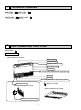
MUCF-13NV - E3 OUTDOOR UNIT Air inlet (back and side) Piping Drain hose Air outlet Drain outlet MCF-13NV - E3 REMOTE CONTROLLER CLOCK RESET 3
3 SPECIFICATION Capacity Model MCF-13NV- E3 Function Cooling Power supply Single phase, 220-240V, 50Hz Capacity kW 3.7 Dehumidification R/h 1.6 Air flow K/h 678 Power outlet A 10 Running current A 6.3-6.3 Power input W 1,310-1,380 A(kW) — Electrical Auxiliary heater data Power factor % 95-91 Starting current A 35-38 Compressor motor current A 5.74-5.72 Fan motor current A 0.56-0.58 Coefficient of performance(C.O.P) 2.82-2.
NOISE CRITERIA CURVES MCF-13NV - MUCF-13NV - E3 SPL(dB(A)) Hi (220-240V) 43-44 90 70 NC-70 60 NC-60 50 NC-50 40 NC-40 30 NC-30 10 APPROXIMATE THRESHOLD OF HEARING FOR CONTINUOUS NOISE 63 125 NC-20 250 500 1000 2000 4000 BAND CENTER FREQUENCIES, Hz SPL(dB(A)) Hi 49 LINE 70 NC-70 60 NC-60 50 NC-50 40 NC-40 30 NC-30 20 APPROXIMATE THRESHOLD OF HEARING FOR CONTINUOUS NOISE 63 125 NC-20 250 500 1000 2000 4000 BAND CENTER FREQUENCIES, Hz 5 WB 24: 80 10 8000 NOTCH
5 OUTLINES AND DIMENSIONS MCF-13NV - Unit: mm E3 114 INDOOR UNIT 80.8 (When installed on the floor) 50cm or more 16 906 112.8 616.5 (When installed on the ceiling) 93 77 143 113 50cm or more 42.5 100cm or more 170 50c mo rm ore 650 50cm or more 180 1100 Gas line 12.7 17.5 56 160 Liquid line 6.
WIRING DIAGRAM MCF-13NV - E3 MODEL WIRING DIAGRAM INDOOR UNIT CIRCUIT BREAKER TB PE GRN/YLW W BLU N L W BRN POWER SUPPLY ~/N 220-240V 50Hz W 3 52C TRANS CN201 TO OUTDOOR UNIT CONNECTING SR142 SR143 CN CN 101 104 N W BLU CN 113 5 220-240v~ 2 W WHT CN 151 5 BLK BLU YLW LDFH LDFL LDFM ELECTRONIC CONTROL P.C BOARD 1 2 3 7 4 6 5 8 WHT ORN RED BRN BLK BLU YLW MF GRN/YLW 6 MV 5 DISPLAY & RECEIVER P.C.
7 REFRIGERANT SYSTEM DIAGRAM Unit:mm MCF-13NV - E3 MUCF-13NV - INDOOR UNIT OUTDOOR UNIT Refrigerant pipe [12.7 (option) (With heat insulation) Indoor heat exchanger Indoor coil thermistor RT12 E3 Stop valve (with service port) Flared connection Distributor Room temperature thermistor RT11 Outdoor heat exchanger Compressor Stop valve Capillary tube Strainer [3.0 ✕[1.6 ✕ 300 Refrigerant pipe [6.35 (option) (With heat insulation) Refrigerant flow in cooling MAX.
8 PERFORMANCE CURVES MCF-13NV - E3 The standard data contained in these specifications apply only to the operation of the air conditioner under normal conditions, Since operating conditions vary according to the areas where these units are installed. The following information has been provided to clarify the operating characteristics of the air conditioner under the conditions indicated by the performance curve.
OUTDOOR LOW PRESSURE AND OUTDOOR UNIT CURRENT COOL operation 1 Both indoor and outdoor units are under the same temperature/humidity condition Dry Bulb temperature (˚C) 20 25 30 2 Air flow should be set at MAX. Relative humidity (%) 50 60 70 3 The unit of pressure has been changed to MPa on the international system of units(SI unit system). f • G) The conversion factor is : 1(MPa • G) =10.2(kgf/f MUCF-13NV - E3 7 8 0.7 220-240V 6 0.6 5 0.5 4 0.4 3 0.
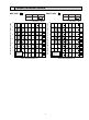
PERFORMANCE DATA COOL operation(220V) MCF-13NV - E3 : MUCF-13NV - E3 CAPACITY : 3.7 kW INPUT : 1310 W SHF : 0.70 INDOOR INDOOR DB(:) WB(:) 21 18 21 20 22 18 22 20 22 22 23 18 23 20 23 22 24 18 24 20 24 22 24 24 25 18 25 20 25 22 25 24 26 18 26 20 26 22 26 24 26 26 27 18 27 20 27 22 27 24 27 26 28 18 28 20 28 22 28 24 28 26 29 18 29 20 29 22 29 24 29 26 30 18 30 20 30 22 30 24 30 26 31 18 31 20 31 22 31 24 31 26 32 18 32 20 32 22 32 24 32 26 NOTE Q 4.35 4.53 4.35 4.53 4.72 4.35 4.53 4.72 4.35 4.53 4.72 4.
PERFORMANCE DATA COOL operation(220V) MCF-13NV - E3 : MUCF-13NV - E3 CAPACITY : 3.7 kW INPUT : 1310 W SHF : 0.70 OUTDOOR DB(:) INDOOR INDOOR 35 40 DB(:) WB(:) Q SHC SHF INPUT Q SHC SHF INPUT 21 18 3.63 1.89 0.52 1284 3.33 1.73 0.52 1362 21 20 3.81 1.52 0.40 1336 3.55 1.42 0.40 1402 22 18 3.63 2.03 0.56 1284 3.33 1.86 0.56 1362 22 20 3.81 1.68 0.44 1336 3.55 1.56 0.44 1402 22 22 4.03 1.29 0.32 1389 3.77 1.21 0.32 1467 23 18 3.63 2.18 0.60 1284 3.33 2.00 0.60 1362 23 20 3.81 1.83 0.48 1336 3.55 1.70 0.
PERFORMANCE DATA COOL operation(240V) MCF-13NV - E3 : MUCF-13NV - E3 CAPACITY : 3.7 kW INPUT : 1380 W SHF : 0.70 INDOOR INDOOR DB(:) WB(:) 21 18 21 20 22 18 22 20 22 22 23 18 23 20 23 22 24 18 24 20 24 22 24 24 25 18 25 20 25 22 25 24 26 18 26 20 26 22 26 24 26 26 27 18 27 20 27 22 27 24 27 26 28 18 28 20 28 22 28 24 28 26 29 18 29 20 29 22 29 24 29 26 30 18 30 20 30 22 30 24 30 26 31 18 31 20 31 22 31 24 31 26 32 18 32 20 32 22 32 24 32 26 NOTE Q 4.35 4.53 4.35 4.53 4.72 4.35 4.53 4.72 4.35 4.53 4.72 4.
PERFORMANCE DATA COOL operation(240V) MCF-13NV - E3 : MUCF-13NV - E3 CAPACITY : 3.7 kW INPUT : 1380 W SHF : 0.70 OUTDOOR DB(:) INDOOR INDOOR 35 40 DB(:) WB(:) Q SHC SHF INPUT Q SHC SHF INPUT 21 18 3.63 1.89 0.52 1352 3.33 1.73 0.52 1435 21 20 3.81 1.52 0.40 1408 3.55 1.42 0.40 1477 22 18 3.63 2.03 0.56 1352 3.33 1.86 0.56 1435 22 20 3.81 1.68 0.44 1408 3.55 1.56 0.44 1477 22 22 4.03 1.29 0.32 1463 3.77 1.21 0.32 1546 23 18 3.63 2.18 0.60 1352 3.33 2.00 0.60 1435 23 20 3.81 1.83 0.48 1408 3.55 1.70 0.
9 MICROPROCESSOR CONTROL WIRELESS REMOTE CONTROLLER MCF-13NV - E3 Once the operation mode are set, the same operation mode can be repeated by simply turning the OPERATE/STOP(ON/OFF) button ON. Indoor unit receives the signal with a beep tone. When the system turns off, 3-minutes time delay will operate to protect system from overload and compressor will not restart for 3 minutes. ) OPERATION 9-1. “I FEEL CONTROL” ( (1) Press OPERATE/STOP(ON/OFF) button on the remote controller.
(4) The initial set temperature is decided by the initial room temperature. Mode Initial room temperature COOL mode of "I FEEL CONTROL" Initial set temperature 26: or more 24: 25: to 26: Initial room temperature minus 2: more than 13:, less than 25: Initial room temperature minus 2: ❈1 DRY mode of "I FEEL CONTROL" ❈1 When the system is restarted with the remote controller, the system operates with the previous set temperature regardless of the the room temperature at restart.
—DRY mode of “I FEEL CONTROL”— The system for dry operation uses the same refrigerant circuit as the cooling circuit. The compressor and the indoor fan are controlled by the temperature. By such controls, indoor air flow amounts will be reduced in order to lower humidity without much room temperature decrease. 1. Indoor fan speed control Indoor fan operates at the set speed by FAN SPEED CONTROL button. However, in AUTO fan operation, fan speed becomes Lo. 2.
9-4. FAN ( ) OPERATION (1) Press OPERATE/STOP (ON/OFF) button. (2) Select FAN mode with the OPERATION SELECT button. (3) Select the desired fan speed. When AUTO, it becomes Lo. Only indoor fan operates. Outdoor unit does not operate. 9-5. AUTO VANE OPERATION (1) Vane motor drive This model is equipped with a stepping motor for the vane. The rotating direction, speed, and angle of the motor are controlled by pulse signals (approx. 12V) transmitted from indoor microprocessor.
9-6. TIMER OPERATION 1. How to set the timer (1) Press OPERATE/STOP(ON/OFF) button to start the air conditioner. (2) Check that the current time is set correctly. NOTE : Timer operation will not work without setting the current time. Initially “AM0:00” blinks at the current time display of TIME MONITOR, so set the current time correctly with CLOCK SET button. (3) Press ON-TIMER, OFF-TIMER button to select the operation. “ ” button ... AUTO START operation (ON timer) “ ” button ...
9-7. EMERGENCY-TEST OPERATION When the remote controller is missing, has failed or the batteries run down, press the EMERGENCY OPERATION switch on the front of the indoor unit. The unit will start and the OPERATION INDICATOR lamp will light. The first 30 minutes of operation is the test run operation. This operation is for servicing. The indoor fan speed runs at high notch and the system is in continuous operation.
10 SERVICE FUNCTIONS MCF-13NV - E3 10-1. TIMER SHORT MODE For service, set time can be shortened by short circuit of JPG and JPS on the electronic control P.C. board. The time will be shortened as follows. 3-minutes time delay : 3-minutes → 3-seconds. AUTO START : 1 hour → 1-minute Short the connector during the timer mode. AUTO STOP : 1 hour → 1-minute } 10-2. P.C. BOARD MODIFICATION FOR INDIVIDUAL OPERATION A maximum of 4 indoor units with wireless remote controllers can be used in a room.
11 TROUBLESHOOTING MCF-13NV - E3 11-1. Cautions on troubleshooting 1. Before troubleshooting, check the following: 1) Check the power supply voltage. 2) Check the indoor/outdoor connecting wire for mis-wiring. 2. Take care the following during servicing. 1) Before servicing the air conditioner, be sure to first turn off the remote controller to stop the main unit, and then after confirming the horizontal vane is closed, turn off the breaker. 2) When removing the electronic control P.C.
11-2. Instruction of troubleshooting Start Indoor unit operates. Outdoor unit doesn’t operate. Outdoor unit operates in only Test Run operation. Outdoor unit doesn’t operate even in Test Run operation. Check room temperatur e thermistor. Refer to D “Check of outdoor unit” on page 26. Indoor unit doesn’t receive the signal from remote controller. Refer to B “Check of receiver P.C. board” on page 25.
MCF-13NV - E3 2. Trouble criterion of main parts Part name Room temperature thermistor Check method and criterion Figure Measure the resistance with a tester. (Part temperature 10°C ~ 30°C) Indoor coil thermistor Normal Abnormal 8kΩ ~ 20kΩ Opened or short-circuited Measure the resistance between the terminals with a tester. (Coil wiring temperature -10°C ~ 40°C) WHT C Compressor C-R C-S Normal Abnormal 1.86~2.28Ω Opened or short-circuited 3.5~4.
A Check of indoor fan motor Indoor fan does not operate. Turn OFF the power supply. Check connector (Fan motor) visually. Yes No Is soldered point normal? Are lead wires connected? No Yes Reconnect the lead wires. Resolder it. Disconnect lead wires from connector (Fan motor) on indoor electronic control P.C. board. Measure resistance between lead wires No.1 and No.4 and then No.3 and No.4 of the fan motor.
C Check of indoor electronic control P.C. board The unit doesn’t operate with the remote controller. Also, the OPERATION INDICATOR lamp doesn’t light up by pressing the EMERGENCY OPERATION switch. Replace the fuse. Yes No Is fuse(F11)blown? Check both “parts side”and “pattern side” of indoor electronic control P.C. board visually. Replace the indoor electronic control P.C. board. Be sure to check both fuse and varistor in any case. Is varistor(NR11)burnt? No Yes Replace the varistor.
TEST POINT DIAGRAM AND VOLTAGE MCF-13NV - E3 Indoor electronic control P.C. board Fan motor power supply Fan motor voltage 220-240V AC 7 5 Lo Hi 6 4 3 2 1 8 Fuse 250V AC 3.15A Power supply input 220-240V AC + – + – } } 12V DC 5V DC CN104 JHA(Release of AUTO RESTART FUNCTION.Refer to page 21.
12 DISASSEMBLY INSTRUCTIONS <"Terminal with lock mechanism" Detaching points> In case of terminal with lock mechanism, detach the terminal as shown below. There are two types ( Refer to (1) and (2)) of the terminal with lock mechanism. The terminal with no lock mechanism can be removed by pulling it out. Check the shape of the terminal and work. (1) Slide the sleeve and check if there is a locking lever or not.
OPERATING PROCEDURE PHOTOS 3. Removing the indoor heat exchanger. Photo 5 (1) Remove the grill. (Refer to 1. (1) (2)) (2) Remove the screws on both side and in front of the front panel. (Photo 5) (3) Remove the screws of the nozzle assembly. (Photo 6) (4) Remove the electronic box. (Refer to 1) (5) Remove the indoor fan motor. (Refer to 2) (6) Remove the screws of the motor support. (7) Remove the fan casing. (Iower) (8) Remove the installations of the drain pan and remove the screws.
12-2. MUCF-13NV- E3 OUTDOOR UNIT OPERATING PROCEDURE PHOTOS 1. Removing the cabinet (1) (2) (3) (4) (5) Remove the Remove the Remove the Remove the Remove the the insides. (6) Remove the (7) Remove the screws of the top panel. screws of the service panel. screws of the cabinet. screws of the front panel and motor support. service panel, and remove the screw from Photo 1 Screws of the front panel and motor support top panel. cabinet.
OPERATING PROCEDURE PHOTOS Photo 5 3. Removing the propeller fan and the outdoor fan motor (1) Remove the cabinet. (Refer to 1.) (2) Remove the propeller fan nut. (3) Remove the propeller fan. NOTE : Loose the propeller fan in the rotating direction for removal. When attaching the propeller fan, align the mark on the propeller fan and the motor shaft cut section. Set the propeller fan in position by using the cut on the shaft and the mark on the propeller fan.
13 PARTS LIST MCF-13NV - E3 (WH) 13-1. INDOOR UNIT STRUCTURAL PARTS 3 13-2. ACCESSORY PART AND REMOTE CONTROLLER 9 5 14 6 17 18 16 13 12 UNION(LIQUID) 1 4 2 UNION(GAS) 10 11 7 8 13-1. INDOOR UNIT STRUCTURAL PARTS Part number that is circled is not shown in the illustration. Symbol in Wiring Diagram Q'ty/unit No. Part No.
13-3. INDOOR UNIT FUNCTIONAL PARTS AND ELECTRICAL PARTS MCF-13NV - E3 (WH) 9 6 8 5 4 11 2 1 3 Part number that are circled are not shown in the illustration. No. Part No. Symbol in Wiring Diagram Part name Q'ty/unit MCF-13NV- E3 (WH) 1 Remark RA4V19- 1 E02 227 300 INDOOR FAN MOTOR 2 E02 179 500 SIROCCO FAN 2 3 E02 179 505 FAN MOTOR RUBBER MOUNT 2 2PCS/SET 4 MF E02 227 375 TERMINAL BLOCK TB 1 FigureA E02 228 375 TERMINAL BLOCK TB 1 FigureB SWITCH & ROOM TEMPERATURE P.C.
18 13-4. OUTDOOR UNIT STRUCTURAL PARTS, ELECTRICAL PARTS AND FUNCTIONAL PARTS MUCF-13NV- E3 8 9 11 12 5 4 10 1 2 3 6 14 7 16 15 17 Part number that are circled are not shown in the illustration. Symbol in Wiring Diagram Q'ty/unit Remark No. Part No.
14 OPTIONAL PARTS 14-1. AIR CLEANING FILTER ● If the air cleaning filter is clogged, it may reduce the air conditioner capacity or cause condensation at the air outlet. ● The air cleaning filter is disposable. The standard usable term is about 4 months. However, if the color of the filter turns to dark brown, replace soon. Remove the air filter and the air cleaning filter together. Separate the air cleaning filter (white bellow type) from the air filter. Model MCF-13NV- Part No. E3 MAC-1200FT 14-2.
HEAD OFFICE MITSUBISHI DENKI BLDG.MARUNOUCHI TOKYO100-8310 TELEX J24532 CABLE MELCO TOKYO CCopyright 1999 MITSUBISHI ELECTRIC ENGINEERING CO., LTD. Issued in Jun. 1999. No.OB239 268 Printed in Japan New publication, effective Jun. 1999. Specifications subject to change without notice.