User's Manual USER’S MANUAL MANUEL UTILISATEUR MANUAL DEL USUARIO 1-1
Index Important Information ................................................................................................................................... English-1 Safety Precautions, Maintenance & Recommended Use ............................................................................ English-3 Contents ....................................................................................................................................................... English-4 Parts Name and Functions .........
DECLARATION OF CONFORMITY This device complies with Part 15 of FCC Rules. Operation is subject to the following two conditions. (1) This device may not cause harmful interference, and (2) this device must accept any interference received, including interference that may cause undesired operation. U.S. Responsible Party: Address: Tel. No.: Mitsubishi Digital Electronics America, Inc. 9351 Jeronimo Road, Irvine, California 92618 U.S.A.
Important Information WARNING TO PREVENT FIRE OR SHOCK HAZARDS, DO NOT EXPOSE THIS UNIT TO RAIN OR MOISTURE. ALSO, DO NOT USE THIS UNIT’S POLARIZED PLUG WITH AN EXTENSION CORD RECEPTACLE OR OTHER OUTLETS UNLESS THE PRONGS CAN BE FULLY INSERTED. REFRAIN FROM OPENING THE CABINET AS THERE ARE HIGH VOLTAGE COMPONENTS INSIDE. REFER SERVICING TO QUALIFIED SERVICE PERSONNEL. CAUTION CAUTION: TO REDUCE THE RISK OF ELECTRIC SHOCK, MAKE SURE POWER CORD IS UNPLUGGED FROM WALL SOCKET.
FOR OPTIMUM PERFORMANCE, PLEASE NOTE THE FOLLOWING WHEN SETTING UP AND USING THE MDT321S LCD COLOR MONITOR: • • • Immediately unplug your monitor from the wall outlet and refer servicing to qualified service personnel under the following conditions: DO NOT OPEN THE MONITOR. There are no user serviceable parts inside and opening or removing covers may expose you to dangerous shock hazards or other risks. Refer all servicing to qualified service personnel.
Contents Your new MDT321S monitor box* should contain the following: • LCD monitor • CD-ROM • Power Cord (3m) for North America • Band x 2 • Power Cord (3m) for EU • Ferrite Core x 2 • Video Signal Cable (4m) • Speaker Plug x 1set (Required for optional Loudspeakers) • User’s Manual • Stand for the Independence x 2 • Wireless Remote Control and AA Batteries • Thumbscrew for stand (M4 x 27) x 2 • Clamper x 3 • Main switch cover • Screw (M4 x 8) x 4 Thumbscrew for stand x 2 Stand
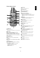
English Parts Name and Functions Control Panel OFF ON Button Location 1 POWER button ( ) 7 DOWN ( ) button Switches the power on/off. See also page 17. Activates the OSD menu when the OSD menu is turned-off. Acts as button to move the highlighted area down to select the adjustment with OSD menu. 2 MUTE button Switches the audio mute ON/OFF. 8 EXIT button Activates the OSD menu when the OSD menu is turned-off. Acts as EXIT button to move to previous menu with OSD menu.
Terminal Panel 1 AC IN connector 7 AUDIO IN 1, 2, 3 Connects with the supplied power cord. To input audio signal from external equipment such as a computer, VCR or DVD player. 2 RGB 1 IN (DVI-D) 8 AUDIO OUT To input digital RGB signals from a computer. To output the audio signal from the AUDIO IN 1, 2 and 3 jack. * This connector does not support analog input. 9 VIDEO IN/OUT 3 RGB 2 IN (mini D-Sub 15 pin) VIDEO IN connector (BNC and RCA): To input a composite video signal.
6 MUTE button To switch the mute function on/off. 7 VOLUME UP button Increases the audio output level. 8 VOLUME DOWN button Decreases the audio output level. 9 PIP (Picture In Picture) button ON/OFF button: PIP ON/OFF. See page 22. INPUT button: Selects the “picture in picture” input signal. CHANGE button: Replaces to the main picture and sub picture. 10 STILL button ON/OFF button: To switch the still picture mode on/off. CAPTURE button: Updates the still picture.
Operating Range for the Remote Control Point the top of the remote control toward the LCD monitor’s remote sensor during button operation. Handling the remote control Use the remote control within a distance of about 7 m/23 ft. from the front of the LCD monitor’s remote control sensor and at a horizontal and vertical angle of within 30° within a distance of about 3 m/10 ft. * Do not subject to strong shock. * Do not allow water or other liquid to splash the remote control.
1. Determine the installation location 3. Connect external equipment (See pages 12-16) CAUTION: DO NOT ATTEMPT TO INSTALL THE LCD MONITOR BY YOURSELF. Installing your LCD display must be done by a qualified technician. Contact your dealer for more information. CAUTION: MOVING OR INSTALLING THE LCD MONITOR MUST BE DONE BY TWO OR MORE PEOPLE. Failure to follow this caution may result in injury if the LCD monitor falls. CAUTION: Do not mount or operate the display upside down, face up, or face down.
10. Recommended Adjustment To reduce the risk of “image persistence”, please adjust the following items based on the application being used. “SCREEN SAVER” (See page 23), “SIDE BORDER COLOR” (See page 23), “DATE & TIME” (See page 26), “SCHEDULE” (See page 26). 11. When the monitor is installed in the portrait position • Remove the stands (feet). • Left edge should be the upper edge from front view. 12. Installing and removing stand Speaker terminal How to install stand 1. Please turn monitor off. 2.
You can attach mounting accessories to the LCD monitor in one of the following two ways: 3. Ventilation Requirements for enclosure mounting 1. In the upright position To allow heat to disperse, leave space between surrounding objects as shown in the diagram below. 4. To avoid falling down Fasten the LCD monitor to wall using a cord or chain, which is sufficient to support the weight of the LCD monitor (approx. 16.4kg). 2.
Connections Before making connections: * First turn off the power of all the attached equipment and make connections. * Refer to the user manual included with each separate piece of equipment. Wiring Diagram LCD monitor Personal computer DVD player Personal computer VCR LCD monitor (second monitor) Equipment with digital interface Attaching the Ferrite Core Mounting Position of Ferrite Core Attach the Ferrite Core to PC Audio Cable.
Connecting your computer to your LCD monitor will enable you to display your computer’s screen image. Some video cards may not display an image correctly. Resolution 640 x 480 800 x 600 1024 x 768 1280 x 768 1360 x 768 1280 x 1024 1600 x 1200 Scanning frequency Horizontal Vertical 31.5kHz 60Hz 37.9kHz 60Hz 48.
Connecting with Digital Interface Equipment Connections can be made with equipment that is equipped with a digital interface compliant with the DVI (Digital Visual Interface) standard. Connect the LCD Monitor to a Computer with a Digital Output • The RGB 1 IN connector also accepts a DVI-D cable. • Input TMDS signals conforming to DVI standards. • To maintain display quality, use a cable with a quality prescribed by DVI standards. • The AUDIO IN 1, 2 and 3 can be used for audio input.
English Connecting a DVD Player with component out Connecting your DVD player to your LCD monitor will enable you to display DVD video. Refer to your DVD player user’s manual for more information. Connect the LCD Monitor to a DVD Player To connect the DVD/HD IN connector (BNC) on the LCD monitor, use a separately available BNC connector cable. You will need a BNC-to-RCA adapter to connect a DVD player with an RCA pin jack to the BNC connector cable (not provided).
Connecting to a Stereo Amplifier You can connect your stereo amplifier to your LCD monitor. Refer to your amplifier owner’s manual for more information. Connect the LCD Monitor to a Stereo Amplifier • Turn on the LCD monitor and the amplifier only after all connections have been made. • Use an RCA cable to connect the AUDIO OUT connector (RCA) on the LCD monitor and the audio input on the amplifier. • Do not reverse the audio left and right jacks. • The AUDIO IN is used for audio input.
English Basic Operation Power ON and OFF Modes The LCD monitor power indicator will turn green while powered on, or red when in off mode. The monitor can be powered on or off using the following three options: 1. Pressing the power button. Note: Before pressing the power button, be sure to turn on the Main Power Switch on the LCD monitor. Power Button 2. Using the remote control. Note: Before operating the remote control, be sure to turn on the Main Power Switch on the LCD monitor. 3.
NORMAL: Display by the inputed signal aspect ratio by PC signal, or display in 4:3 aspect ratio at DVD/HD or VIDEO signal. FULL: Display in entire screen. WIDE: Expand 16:9 letter box signal to entire screen. ZOOM (DYNAMIC): Expand 4:3 pictures to the entire screen with non-linearity. (Some around image will be cut by expansion.
Press MENU button to open Main menu. Press UP or DOWN button to select sub-menu. Press SET button to decide. Press UP or DOWN, and PLUS or MINUS button to select function, or control which you like. Press SET button to decide. Press MENU or EXIT button to exit. Press UP or DOWN button to select. Press INPUT button to decide. Press UP or DOWN, and PLUS or MINUS button to select function, or control which you like. Press INPUT button to decide. Press EXIT button to exit.
Adjust the tint of the screen. PICTURE BRIGHTNESS CONTRAST SHARPNESS TINT COLOR BLACK LEVEL NOISE REDUCTION TINT TINT 32 + -:ADJ EXIT :RETURN MENU :EXIT MENU Press + button to Skin color becomes greenish. Press - button to Skin color becomes purplish. :SEL SET :NEXT EXIT :RETURN MENU :EXIT MENU *:INPUT DVD/HD, VIDEO only Adjust the color depth of the screen.
*:INPUT RGB1/2/3 only V RESOLUTION 768 + -:ADJ EXIT :RETURN MENU :EXIT MENU :SEL SET :NEXT EXIT :RETURN MENU :EXIT MENU SCREEN H POSITION V POSITION CLOCK CLOCK PHASE H RESOLUTION V RESOLUTION ZOOM MODE SCREEN RESET ZOOM MODE CUSTOM OFF :SEL SET :NEXT EXIT :RETURN MENU :EXIT MENU :SEL SET :NEXT EXIT :RETURN MENU :EXIT MENU Adjusts the vertical size by increasing or decreasing the setting. Press + button to expand the height of the image on the screen.
Main-Menu MAIN MENU PICTURE SCREEN AUDIO PIP CONFIGURATION 1 CONFIGURATION 2 ADVANCED OPTION PICTURE IN PICTURE :SEL SET :NEXT EXIT :RETURN MENU :EXIT MENU Sub-Menu PIP PIP SIZE PIP AUDIO PIP RESET PIP SIZE Selecting the size of picture inserted at the “Picture-in-Picture” (PIP) mode. PIP SIZE LARGE MIDDLE SMALL :SEL EXIT :RETURN MENU :EXIT MENU “Large”, “Middle” and “Small” are available.
SCREEN SAVER CONFIGURATION 1 AUTO SETUP AUTO ADJUST AUTO BRIGHTNESS POWER SAVE LANGUAGE SCREEN SAVER SIDE BORDER COLOR :SEL SET :NEXT EXIT :RETURN MENU :EXIT MENU COLOR SYSTEM *:INPUT VIDEO only SIDE BORDER COLOR CONFIGURATION 1 POWER SAVE LANGUAGE SCREEN SAVER COLOR SYSTEM SIDE BORDER COLOR CONFIGURATION RESET FACTORY RESET :SEL SET :NEXT EXIT :RETURN MENU :EXIT MENU CONFIGURATION 1 AUTO BRIGHTNESS POWER SAVE LANGUAGE POWER SAVE COLOR SYSTEM SIDE BORDER COLOR CONFIGURATION RESET FACTORY RESET SCREEN
OSD TURN OFF CONFIGURATION 2 LONG CABLE MANUAL OSD TURN OFF INFORMATION OSD OFF TIMER OSD POSITION INPUT DETECT MONITOR INFORMATION OSD TURN OFF 10 SEC. + -:ADJ EXIT :RETURN MENU :EXIT MENU :SEL SET :NEXT EXIT :RETURN MENU :EXIT MENU INFORMATION OSD CONFIGURATION 2 LONG CABLE MANUAL OSD TURN OFF INFORMATION OSD OFF TIMER OSD POSITION INPUT DETECT MONITOR INFORMATION Selects the information OSD display or not.
MAIN MENU PICTURE SCREEN AUDIO PIP CONFIGURATION 1 CONFIGURATION 2 ADVANCED OPTION ADVANCED OPTION :SEL SET :NEXT EXIT :RETURN MENU :EXIT MENU Sub-Menu S-VIDEO MODE ADVANCED OPTION S-VIDEO MODE BLACK LEVEL EXPANSION GAMMA SELECTION SCAN MODE SCAN CONVERSION FILM MODE TILING S-VIDEO MODE PRIORITY / EXIT + -:SEL SEPARATE :RETURN MENU :EXIT MENU :SEL SET :NEXT EXIT :RETURN MENU :EXIT MENU INPUT RESOLUTION *:INPUT RGB2/3 only BLACK LEVEL EXPANSION *:INPUT VIDEO, DVD/HD only GAMMA SELECTION ADVA
TILING demonstrates multiple screens. This feature provides a single large screen using up to 16 monitors. It will be able to divide up to 4 each H and V. This requires you to feed the PC output into each of the monitors through a distributor.
Please be aware that LCD Technology may experience a phenomena known as Image Persistence. Image Persistence occurs when a residual or “ghost” image of a previous image remains visible on the screen. Unlike CRT monitors, LCD monitors’ image persistence is not permanent, but constant images being displayed for a long period of time should be avoided. To alleviate image persistence, turn off the monitor for as long as the previous image was displayed.
Controlling the LCD monitor via RS-232C Remote Control This LCD monitor can be controlled by connecting a personal computer with a RS-232C terminal. Functions that can be controlled by a personal computer are: • Power ON or OFF • Switching between input signals Connection LCD Monitor + PC RS-232C Cable NOTE: If your PC (IBM or IBM compatible) is equipped only with a 25-pin serial port connector, a 25-pin serial port adapter is required. Contact your dealer for details.
(1) The command from a computer to the LCD monitor will be sent in 600ms. (2) The LCD monitor will send a return command 600ms* after it has received and encoded. If the command isn’t received correctly, the LCD monitor will not send the return command. (3) The personal computer checks the command and confirms if the command, which has been sent, has been executed or not. (4) This LCD monitor sends various codes other than return code.
Features Reduced Footprint: Provides the ideal solution for environments requiring superior image quality but with size and weight limitations. The monitor’s small footprint and low weight allow it to be moved or transported easily from one location to another. Color Control Systems: Allows you to adjust the colors on your screen and customize the color accuracy of your monitor to a variety of standards.
No picture • The signal cable should be completely connected to the display card/computer. • The display card should be completely seated in its slot. • Front Power Switch and computer power switch should be in the ON position. • Check to make sure that a supported mode has been selected on the display card or system being used. (Please consult display card or system manual to change graphics mode.) • Check the monitor and your display card with respect to compatibility and recommended settings.
Specifications Product Specifications Analog Input LCD Module 32" / 80.0cm 0.511mm 1366 x 768 dots Over 16 million colors (depending on video card used) 500cd/m2 (Typ.) 600:1 20ms (Tr+Tf) Up 88°/ Down 88°/ Left 88°/ Right 88° (typ) @ CR>10 875 mm/34.4 inches Diagonal: Pixel Pitch: Resolution: Color: Brightness: Contrast Ratio: Response time: Viewing Angle: Design View Distance: Frequency 15.625/15.734kHz, 31.5kHz - 91.1kHz 50.0/58.0 - 85.0 Hz 31.5kHz - 91.1kHz 50.0/58.0 - 85.0 Hz Pixel Clock 25.
English Pin Assignment 1) Analog RGB input (MiniDsub15p): R G B 2 Pin No Name 1 Video Signal Red 2 Video Signal Green 3 Video Signal Blue 4 GND 5 DDC-GND 6 Red-GND 7 Green-GND 8 Blue-GND Mini D-SUB 15P 1 9 +5V (DDC) 10 SYNC-GND 11 GND 12 DDC-SDA 13 H-SYNC 14 V-SYNC 15 DDC-SCL 5 6 10 11 15 2) S-VIDEO input: V I D E O Pin No Name 1 GND 2 GND 3 Y (Luminance) 4 C (Chroma) 3) Digital RGB input (DVI-D): R G B 1 Pin - Assignment of DVI connector: 8 1 TX2- 9 TX1-
MITSUBISHI Contact Information North America Europe MESCA (Mitsubishi Electric Sales Canada Inc.) http://www.mitsubishielectric.ca Information Technologies Group, 4299 14th Avenue, Markham, Ontario L3R 0J2, Canada Sales Phone: +1-(905) 475-7728 Fax: +1-(905) 475-7958 E-mail: projectors@mitsubishielectric.ca Technical Phone: +1-(905) 475-7728 Fax: +1-(905) 475-7958 Customer Care E-mail: support@mitsubishielectric.ca MEU-FRA (Mitsubishi Electric Europe B.