
Instruction Manual
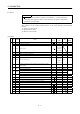
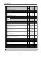

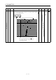
Table Of Contents
- Safety Instructions
- COMPLIANCE WITH EC DIRECTIVES
- CONFORMANCE WITH UL/C-UL STANDARD
- <
> - CONTENTS
- Optional Servo Motor Instruction Manual CONTENTS
- 1. FUNCTIONS AND CONFIGURATION
- 2. INSTALLATION
- 3. SIGNALS AND WIRING
- 3.1 Standard connection example
- 3.2 Internal connection diagram of servo amplifier
- 3.3 I/O signals
- 3.4 Detailed description of the signals
- 3.5 Alarm occurrence timing chart
- 3.6 Interfaces
- 3.7 Input power supply circuit
- 3.8 Connection of servo amplifier and servo motor
- 3.9 Servo motor with electromagnetic brake
- 3.10 Grounding
- 3.11 Servo amplifier terminal block (TE2) wiring method
- 3.12 Instructions for the 3M connector
- 3.13 Power line circuit of the MR-J2S-11KA to MR-J2S-22KA
- 4. OPERATION
- 5. PARAMETERS
- 6. DISPLAY AND OPERATION
- 7. GENERAL GAIN ADJUSTMENT
- 8. SPECIAL ADJUSTMENT FUNCTIONS
- 9. INSPECTION
- 10. TROUBLESHOOTING
- 11. OUTLINE DIMENSION DRAWINGS
- 12. CHARACTERISTICS
- 13. OPTIONS AND AUXILIARY EQUIPMENT
- 13.1 Options
- 13.1.1 Regenerative brake options
- 13.1.2 Brake unit
- 13.1.3 Power regeneration converter
- 13.1.4 External dynamic brake
- 13.1.5 Cables and connectors
- 13.1.6 Junction terminal block (MR-TB20)
- 13.1.7 Maintenance junction card (MR-J2CN3TM)
- 13.1.8 Battery (MR-BAT, A6BAT)
- 13.1.9 MR Configurator (Servo configurations software)
- 13.1.10 Power regeneration common converter
- 13.1.11 Heat sink outside mounting attachment (MR-JACN)
- 13.2 Auxiliary equipment
- 13.2.1 Recommended wires
- 13.2.2 No-fuse breakers, fuses, magnetic contactors
- 13.2.3 Power factor improving reactors
- 13.2.4 Power factor improving DC reactors
- 13.2.5 Relays
- 13.2.6 Surge absorbers
- 13.2.7 Noise reduction techniques
- 13.2.8 Leakage current breaker
- 13.2.9 EMC filter
- 13.2.10 Setting potentiometers for analog inputs
- 13.1 Options
- 14. COMMUNICATION FUNCTIONS
- 14.1 Configuration
- 14.2 Communication specifications
- 14.3 Protocol
- 14.4 Character codes
- 14.5 Error codes
- 14.6 Checksum
- 14.7 Time-out operation
- 14.8 Retry operation
- 14.9 Initialization
- 14.10 Communication procedure example
- 14.11 Command and data No. list
- 14.12 Detailed explanations of commands
- 14.12.1 Data processing
- 14.12.2 Status display
- 14.12.3 Parameter
- 14.12.4 External I/O pin statuses (DIO diagnosis)
- 14.12.5 Disable/enable of external I/O signals (DIO)
- 14.12.6 External input signal ON/OFF (test operation)
- 14.12.7 Test operation mode
- 14.12.8 Output signal pin ON/OFF output signal (DO) forced output
- 14.12.9 Alarm history
- 14.12.10 Current alarm
- 14.12.11 Other commands
- 15. ABSOLUTE POSITION DETECTION SYSTEM
- 15.1 Outline
- 15.2 Specifications
- 15.3 Battery installation procedure
- 15.4 Standard connection diagram
- 15.5 Signal explanation
- 15.6 Startup procedure
- 15.7 Absolute position data transfer protocol
- 15.8 Examples of use
- 15.9 Confirmation of absolute position detection data
- 15.10 Absolute position data transfer errors
- Appendix
- REVISIONS
5 - 4
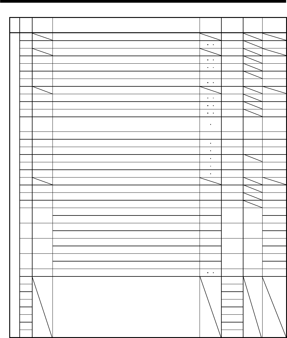
5. PARAMETERS
No. Symbol Name
Control
mode
Initial
value
Unit
Customer
setting
50 For manufacturer setting 0000
51 *OP6 Function selection 6 P S T 0000
52 For manufacturer setting 0000
53 *OP8 Function selection 8 P S T 0000
54 *OP9 Function selection 9 P S T 0000
55 *OPA Function selection A P 0000
56 SIC Serial communication time-out selection P S T0 s
57 For manufacturer setting 10
58 NH1 Machine resonance suppression filter 1 P S T 0000
59 NH2 Machine resonance suppression filter 2 P S T 0000
60 LPF Low-pass filter, adaptive vibration suppression control P S T 0000
61 GD2B Ratio of load inertia moment to Servo motor inertia moment 2 P S70
0.1
times
62 PG2B Position control gain 2 changing ratio P 100 %
63 VG2B Speed control gain 2 changing ratio P S 100 %
64 VICB Speed integral compensation changing ratio P S 100 %
65 *CDP Gain changing selection P S 0000
66 CDS Gain changing condition P S10(Note3)
67 CDT Gain changing time constant P S1ms
68 For manufacturer setting 0
69 CMX2 Command pulse multiplying factor numerator 2 P 1
70 CMX3 Command pulse multiplying factor numerator 3 P 1
71 CMX4 Command pulse multiplying factor numerator 4 P 1
Internal speed command 4 S
72 SC4
Internal speed limit 4 T
200 r/min
Internal speed command 5 S
73 SC5
Internal speed limit 5 T
300 r/min
Internal speed command 6 S
74 SC6
Internal speed limit 6 T
500 r/min
Internal speed command 7 S
75 SC7
Internal speed limit 7 T
800 r/min
76 TL2 Internal torque limit 2 P S T 100 %
77 100
78 10000
79 10
80 10
81 100
82 100
83 100
Expansion parameters 2
84
For manufacturer setting
0000
Note 1. The setting of "0" provides the rated servo motor speed.
2. Depends on the servo amplifier.
3. Depends on the parameter No. 65 setting.