
Instruction Manual
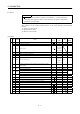
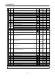

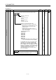
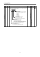
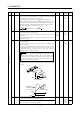
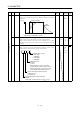
Table Of Contents
- Safety Instructions
- COMPLIANCE WITH EC DIRECTIVES
- CONFORMANCE WITH UL/C-UL STANDARD
- <
> - CONTENTS
- Optional Servo Motor Instruction Manual CONTENTS
- 1. FUNCTIONS AND CONFIGURATION
- 2. INSTALLATION
- 3. SIGNALS AND WIRING
- 3.1 Standard connection example
- 3.2 Internal connection diagram of servo amplifier
- 3.3 I/O signals
- 3.4 Detailed description of the signals
- 3.5 Alarm occurrence timing chart
- 3.6 Interfaces
- 3.7 Input power supply circuit
- 3.8 Connection of servo amplifier and servo motor
- 3.9 Servo motor with electromagnetic brake
- 3.10 Grounding
- 3.11 Servo amplifier terminal block (TE2) wiring method
- 3.12 Instructions for the 3M connector
- 3.13 Power line circuit of the MR-J2S-11KA to MR-J2S-22KA
- 4. OPERATION
- 5. PARAMETERS
- 6. DISPLAY AND OPERATION
- 7. GENERAL GAIN ADJUSTMENT
- 8. SPECIAL ADJUSTMENT FUNCTIONS
- 9. INSPECTION
- 10. TROUBLESHOOTING
- 11. OUTLINE DIMENSION DRAWINGS
- 12. CHARACTERISTICS
- 13. OPTIONS AND AUXILIARY EQUIPMENT
- 13.1 Options
- 13.1.1 Regenerative brake options
- 13.1.2 Brake unit
- 13.1.3 Power regeneration converter
- 13.1.4 External dynamic brake
- 13.1.5 Cables and connectors
- 13.1.6 Junction terminal block (MR-TB20)
- 13.1.7 Maintenance junction card (MR-J2CN3TM)
- 13.1.8 Battery (MR-BAT, A6BAT)
- 13.1.9 MR Configurator (Servo configurations software)
- 13.1.10 Power regeneration common converter
- 13.1.11 Heat sink outside mounting attachment (MR-JACN)
- 13.2 Auxiliary equipment
- 13.2.1 Recommended wires
- 13.2.2 No-fuse breakers, fuses, magnetic contactors
- 13.2.3 Power factor improving reactors
- 13.2.4 Power factor improving DC reactors
- 13.2.5 Relays
- 13.2.6 Surge absorbers
- 13.2.7 Noise reduction techniques
- 13.2.8 Leakage current breaker
- 13.2.9 EMC filter
- 13.2.10 Setting potentiometers for analog inputs
- 13.1 Options
- 14. COMMUNICATION FUNCTIONS
- 14.1 Configuration
- 14.2 Communication specifications
- 14.3 Protocol
- 14.4 Character codes
- 14.5 Error codes
- 14.6 Checksum
- 14.7 Time-out operation
- 14.8 Retry operation
- 14.9 Initialization
- 14.10 Communication procedure example
- 14.11 Command and data No. list
- 14.12 Detailed explanations of commands
- 14.12.1 Data processing
- 14.12.2 Status display
- 14.12.3 Parameter
- 14.12.4 External I/O pin statuses (DIO diagnosis)
- 14.12.5 Disable/enable of external I/O signals (DIO)
- 14.12.6 External input signal ON/OFF (test operation)
- 14.12.7 Test operation mode
- 14.12.8 Output signal pin ON/OFF output signal (DO) forced output
- 14.12.9 Alarm history
- 14.12.10 Current alarm
- 14.12.11 Other commands
- 15. ABSOLUTE POSITION DETECTION SYSTEM
- 15.1 Outline
- 15.2 Specifications
- 15.3 Battery installation procedure
- 15.4 Standard connection diagram
- 15.5 Signal explanation
- 15.6 Startup procedure
- 15.7 Absolute position data transfer protocol
- 15.8 Examples of use
- 15.9 Confirmation of absolute position detection data
- 15.10 Absolute position data transfer errors
- Appendix
- REVISIONS
5 - 8
5. PARAMETERS
Class No. Symbol Name and function
Initial
value
Unit
Setting
range
Control
mode
5 INP In-position range
Used to set the in-position (INP) output range in the command pulse
increments prior to electronic gear calculation.
For example, when you want to set 100
m when the ballscrew is
directly coupled, the lead is 10mm, the feedback pulse count is 131072
pulses/rev, and the electronic gear numerator (CMX)/electronic gear
denominator (CDV) is 16384/125 (setting in units of 10
m per pulse),
set "10" as indicated by the following expression.
100 10
6
10 10
3
131072[pulse/rev]
16384
125
10
100 pulse 0
to
10000
P
6 PG1 Position loop gain 1
Used to set the gain of position loop.
Increase the gain to improve trackability in response to the position
command.
When auto turning mode 1,2 is selected, the result of auto turning is
automatically used.
7kW or
less: 35
11kW or
more: 19
red/s 4
to
2000
P
Position command acceleration/deceleration time constant
(position smoothing)
Used to set the time constant of a low pass filter in response to the
position command.
You can use parameter No. 55 to choose the primary delay or linear
acceleration/deceleration control system. When you choose linear
acceleration/deceleration, the setting range is 0 to 10ms. Setting of
longer than 10ms is recognized as 10ms.
POINT
7PST
When you have chosen linear acceleration/deceleration, do not
select control selection (parameter No. 0) and restart after
instantaneous power failure (parameter No. 20). Doing so will
cause the servo motor to make a sudden stop at the time of
position control switching or restart.
3ms0
to
20000
P
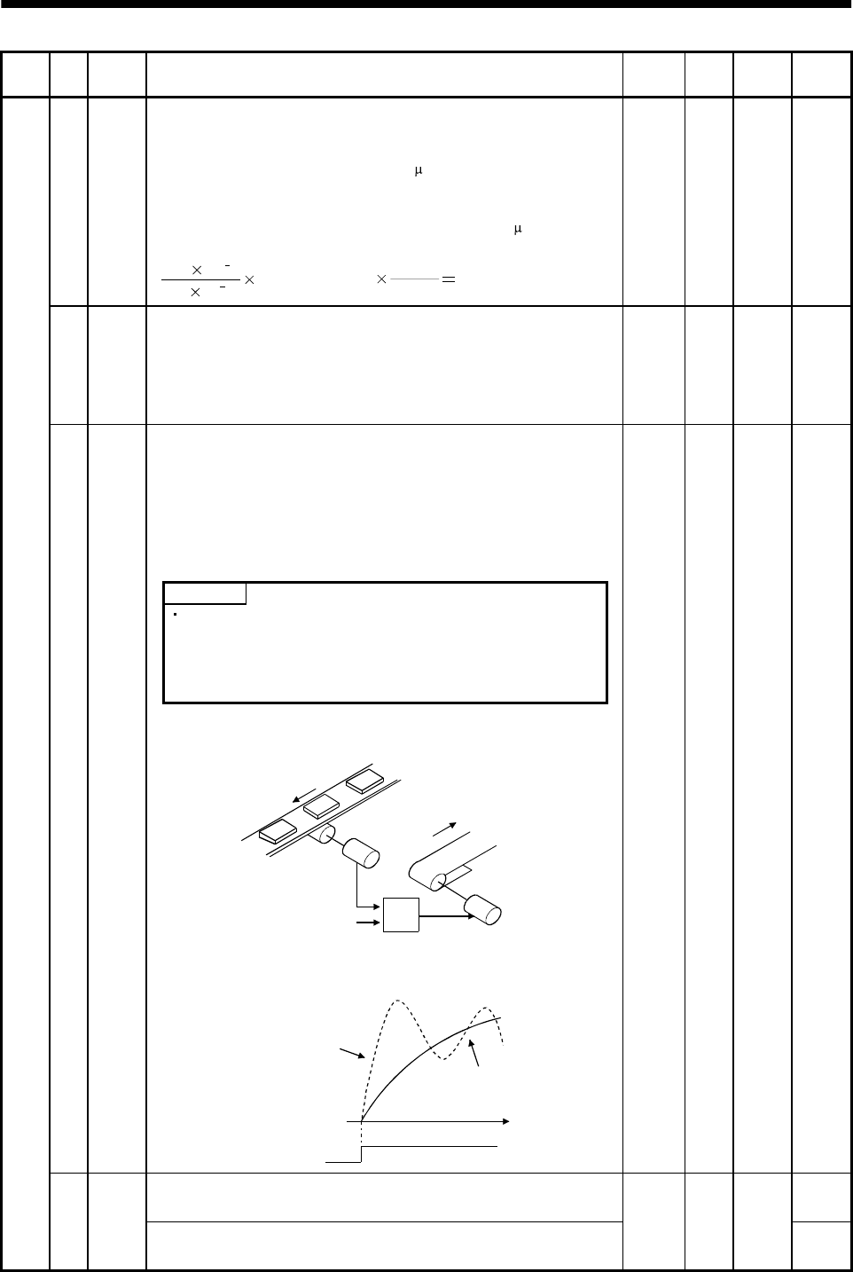
Example: When a command is given from a synchronizing detector,
synchronous operation can be started smoothly if started during line
operation.
Synchronizing
detector
Start
Servo amplifier
Servo motor
Without time
constant setting
Servo motor
speed
Start
With time
constant setting
ON
OFF
t
Internal speed command 1
Used to set speed 1 of internal speed commands.
S
Basic parameters
8SC1
Internal speed limit 1
Used to set speed 1 of internal speed limits.
100 r/min
0 to
instan-
taneous
permi-
ssible
speed
T