
Instruction Manual
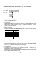


Table Of Contents
- Safety Instructions
- COMPLIANCE WITH EC DIRECTIVES
- CONFORMANCE WITH UL/C-UL STANDARD
- <
> - CONTENTS
- Optional Servo Motor Instruction Manual CONTENTS
- 1. FUNCTIONS AND CONFIGURATION
- 2. INSTALLATION
- 3. SIGNALS AND WIRING
- 3.1 Standard connection example
- 3.2 Internal connection diagram of servo amplifier
- 3.3 I/O signals
- 3.4 Detailed description of the signals
- 3.5 Alarm occurrence timing chart
- 3.6 Interfaces
- 3.7 Input power supply circuit
- 3.8 Connection of servo amplifier and servo motor
- 3.9 Servo motor with electromagnetic brake
- 3.10 Grounding
- 3.11 Servo amplifier terminal block (TE2) wiring method
- 3.12 Instructions for the 3M connector
- 3.13 Power line circuit of the MR-J2S-11KA to MR-J2S-22KA
- 4. OPERATION
- 5. PARAMETERS
- 6. DISPLAY AND OPERATION
- 7. GENERAL GAIN ADJUSTMENT
- 8. SPECIAL ADJUSTMENT FUNCTIONS
- 9. INSPECTION
- 10. TROUBLESHOOTING
- 11. OUTLINE DIMENSION DRAWINGS
- 12. CHARACTERISTICS
- 13. OPTIONS AND AUXILIARY EQUIPMENT
- 13.1 Options
- 13.1.1 Regenerative brake options
- 13.1.2 Brake unit
- 13.1.3 Power regeneration converter
- 13.1.4 External dynamic brake
- 13.1.5 Cables and connectors
- 13.1.6 Junction terminal block (MR-TB20)
- 13.1.7 Maintenance junction card (MR-J2CN3TM)
- 13.1.8 Battery (MR-BAT, A6BAT)
- 13.1.9 MR Configurator (Servo configurations software)
- 13.1.10 Power regeneration common converter
- 13.1.11 Heat sink outside mounting attachment (MR-JACN)
- 13.2 Auxiliary equipment
- 13.2.1 Recommended wires
- 13.2.2 No-fuse breakers, fuses, magnetic contactors
- 13.2.3 Power factor improving reactors
- 13.2.4 Power factor improving DC reactors
- 13.2.5 Relays
- 13.2.6 Surge absorbers
- 13.2.7 Noise reduction techniques
- 13.2.8 Leakage current breaker
- 13.2.9 EMC filter
- 13.2.10 Setting potentiometers for analog inputs
- 13.1 Options
- 14. COMMUNICATION FUNCTIONS
- 14.1 Configuration
- 14.2 Communication specifications
- 14.3 Protocol
- 14.4 Character codes
- 14.5 Error codes
- 14.6 Checksum
- 14.7 Time-out operation
- 14.8 Retry operation
- 14.9 Initialization
- 14.10 Communication procedure example
- 14.11 Command and data No. list
- 14.12 Detailed explanations of commands
- 14.12.1 Data processing
- 14.12.2 Status display
- 14.12.3 Parameter
- 14.12.4 External I/O pin statuses (DIO diagnosis)
- 14.12.5 Disable/enable of external I/O signals (DIO)
- 14.12.6 External input signal ON/OFF (test operation)
- 14.12.7 Test operation mode
- 14.12.8 Output signal pin ON/OFF output signal (DO) forced output
- 14.12.9 Alarm history
- 14.12.10 Current alarm
- 14.12.11 Other commands
- 15. ABSOLUTE POSITION DETECTION SYSTEM
- 15.1 Outline
- 15.2 Specifications
- 15.3 Battery installation procedure
- 15.4 Standard connection diagram
- 15.5 Signal explanation
- 15.6 Startup procedure
- 15.7 Absolute position data transfer protocol
- 15.8 Examples of use
- 15.9 Confirmation of absolute position detection data
- 15.10 Absolute position data transfer errors
- Appendix
- REVISIONS

2
3.8.2 Connection diagram.........................................................................................................................3-50
3.8.3 I/O terminals....................................................................................................................................3-52
3.9 Servo motor with electromagnetic brake .............................................................................................3-54
3.10 Grounding .............................................................................................................................................3-57
3.11 Servo amplifier terminal block (TE2) wiring method.......................................................................3-58
3.11.1 For the servo amplifier produced later than Jan. 2006.............................................................3-58
3.11.2 For the servo amplifier produced earlier than Dec. 2005..........................................................3-60
3.12 Instructions for the 3M connector.......................................................................................................3-61
3.13 Power line circuit of the MR-J2S-11KA to MR-J2S-22KA...............................................................3-62
3.13.1 Connection example ......................................................................................................................3-62
3.13.2 Servo amplifier terminals.............................................................................................................3-63
3.13.3 Servo motor terminals...................................................................................................................3-64
4. OPERATION 4- 1 to 4- 6
4.1 When switching power on for the first time..........................................................................................4- 1
4.2 Startup......................................................................................................................................................4- 2
4.2.1 Selection of control mode..................................................................................................................4- 2
4.2.2 Position control mode.......................................................................................................................4- 2
4.2.3 Speed control mode...........................................................................................................................4- 4
4.2.4 Torque control mode.........................................................................................................................4- 5
4.3 Multidrop communication ......................................................................................................................4- 6
5. PARAMETERS 5- 1 to 5- 34
5.1 Parameter list..........................................................................................................................................5- 1
5.1.1 Parameter write inhibit...................................................................................................................5- 1
5.1.2 Lists....................................................................................................................................................5- 2
5.2 Detailed description ...............................................................................................................................5-26
5.2.1 Electronic gear .................................................................................................................................5-26
5.2.2 Analog monitor.................................................................................................................................5-30
5.2.3 Using forward/reverse rotation stroke end to change the stopping pattern..............................5-33
5.2.4 Alarm history clear..........................................................................................................................5-33
5.2.5 Position smoothing ..........................................................................................................................5-34
6. DISPLAY AND OPERATION 6- 1 to 6-16
6.1 Display flowchart.....................................................................................................................................6- 1
6.2 Status display ..........................................................................................................................................6- 2
6.2.1 Display examples..............................................................................................................................6- 2
6.2.2 Status display list.............................................................................................................................6- 3
6.2.3 Changing the status display screen................................................................................................6- 4
6.3 Diagnostic mode.......................................................................................................................................6- 5
6.4 Alarm mode..............................................................................................................................................6- 7
6.5 Parameter mode ......................................................................................................................................6- 8
6.6 External I/O signal display.....................................................................................................................6- 9
6.7 Output signal (DO) forced output.........................................................................................................6-12
6.8 Test operation mode...............................................................................................................................6-13
6.8.1 Mode change.....................................................................................................................................6-13
6.8.2 Jog operation....................................................................................................................................6-14