
Instruction Manual
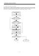
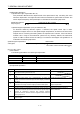
Table Of Contents
- Safety Instructions
- COMPLIANCE WITH EC DIRECTIVES
- CONFORMANCE WITH UL/C-UL STANDARD
- <
> - CONTENTS
- Optional Servo Motor Instruction Manual CONTENTS
- 1. FUNCTIONS AND CONFIGURATION
- 2. INSTALLATION
- 3. SIGNALS AND WIRING
- 3.1 Standard connection example
- 3.2 Internal connection diagram of servo amplifier
- 3.3 I/O signals
- 3.4 Detailed description of the signals
- 3.5 Alarm occurrence timing chart
- 3.6 Interfaces
- 3.7 Input power supply circuit
- 3.8 Connection of servo amplifier and servo motor
- 3.9 Servo motor with electromagnetic brake
- 3.10 Grounding
- 3.11 Servo amplifier terminal block (TE2) wiring method
- 3.12 Instructions for the 3M connector
- 3.13 Power line circuit of the MR-J2S-11KA to MR-J2S-22KA
- 4. OPERATION
- 5. PARAMETERS
- 6. DISPLAY AND OPERATION
- 7. GENERAL GAIN ADJUSTMENT
- 8. SPECIAL ADJUSTMENT FUNCTIONS
- 9. INSPECTION
- 10. TROUBLESHOOTING
- 11. OUTLINE DIMENSION DRAWINGS
- 12. CHARACTERISTICS
- 13. OPTIONS AND AUXILIARY EQUIPMENT
- 13.1 Options
- 13.1.1 Regenerative brake options
- 13.1.2 Brake unit
- 13.1.3 Power regeneration converter
- 13.1.4 External dynamic brake
- 13.1.5 Cables and connectors
- 13.1.6 Junction terminal block (MR-TB20)
- 13.1.7 Maintenance junction card (MR-J2CN3TM)
- 13.1.8 Battery (MR-BAT, A6BAT)
- 13.1.9 MR Configurator (Servo configurations software)
- 13.1.10 Power regeneration common converter
- 13.1.11 Heat sink outside mounting attachment (MR-JACN)
- 13.2 Auxiliary equipment
- 13.2.1 Recommended wires
- 13.2.2 No-fuse breakers, fuses, magnetic contactors
- 13.2.3 Power factor improving reactors
- 13.2.4 Power factor improving DC reactors
- 13.2.5 Relays
- 13.2.6 Surge absorbers
- 13.2.7 Noise reduction techniques
- 13.2.8 Leakage current breaker
- 13.2.9 EMC filter
- 13.2.10 Setting potentiometers for analog inputs
- 13.1 Options
- 14. COMMUNICATION FUNCTIONS
- 14.1 Configuration
- 14.2 Communication specifications
- 14.3 Protocol
- 14.4 Character codes
- 14.5 Error codes
- 14.6 Checksum
- 14.7 Time-out operation
- 14.8 Retry operation
- 14.9 Initialization
- 14.10 Communication procedure example
- 14.11 Command and data No. list
- 14.12 Detailed explanations of commands
- 14.12.1 Data processing
- 14.12.2 Status display
- 14.12.3 Parameter
- 14.12.4 External I/O pin statuses (DIO diagnosis)
- 14.12.5 Disable/enable of external I/O signals (DIO)
- 14.12.6 External input signal ON/OFF (test operation)
- 14.12.7 Test operation mode
- 14.12.8 Output signal pin ON/OFF output signal (DO) forced output
- 14.12.9 Alarm history
- 14.12.10 Current alarm
- 14.12.11 Other commands
- 15. ABSOLUTE POSITION DETECTION SYSTEM
- 15.1 Outline
- 15.2 Specifications
- 15.3 Battery installation procedure
- 15.4 Standard connection diagram
- 15.5 Signal explanation
- 15.6 Startup procedure
- 15.7 Absolute position data transfer protocol
- 15.8 Examples of use
- 15.9 Confirmation of absolute position detection data
- 15.10 Absolute position data transfer errors
- Appendix
- REVISIONS
7 - 4
7. GENERAL GAIN ADJUSTMENT
7.2.2 Auto tuning mode operation
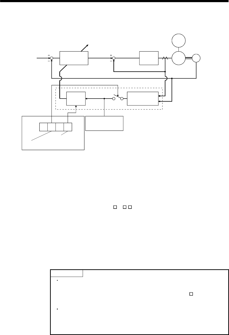
The block diagram of real-time auto tuning is shown below.
Servo
motor
Command
Automatic setting
Control gains
PG1,VG1
PG2,VG2,VIC
Current
control
Current feedback
Load inertia
moment
Encoder
Position/speed
feedback
Real-time auto
tuning section
Speed feedback
Load inertia
moment ratio
estimation section
Gain
table
Parameter No. 2
Gain adjustment
mode selection
First digit
Response level
setting
Parameter No. 34
Load inertia moment
ratio estimation value
Set 0 or 1 to turn on.
Switch
When a servo motor is accelerated/decelerated, the load inertia moment ratio estimation section always
estimates the load inertia moment ratio from the current and speed of the servo motor. The results of
estimation are written to parameter No. 34 (the ratio of load inertia moment to servo motor). These
results can be confirmed on the status display screen of the MR Configurator (servo configuration
software) section.
If the value of the load inertia moment ratio is already known or if estimation cannot be made properly,
chose the "auto tuning mode 2" (parameter No.2:
2 ) to stop the estimation of the load inertia
moment ratio (Switch in above diagram turned off), and set the load inertia moment ratio (parameter No.
34) manually.
From the preset load inertia moment ratio (parameter No. 34) value and response level (The first digit of
parameter No. 2), the optimum control gains are automatically set on the basis of the internal gain tale.
The auto tuning results are saved in the EEP-ROM of the servo amplifier every 60 minutes since power-
on. At power-on, auto tuning is performed with the value of each control gain saved in the EEP-ROM
being used as an initial value.
POINT
If sudden disturbance torque is imposed during operation, the estimation
of the inertia moment ratio may malfunction temporarily. In such a case,
choose the "auto tuning mode 2" (parameter No. 2: 020
) and set the
correct load inertia moment ratio in parameter No. 34.
When any of the auto tuning mode 1, auto tuning mode 2 and manual
mode 1 settings is changed to the manual mode 2 setting, the current
control gains and load inertia moment ratio estimation value are saved in
the EEP-ROM.