
Instruction Manual
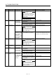
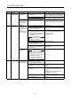
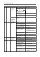
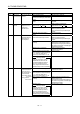
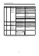
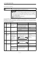
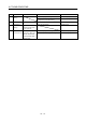
Table Of Contents
- Safety Instructions
- COMPLIANCE WITH EC DIRECTIVES
- CONFORMANCE WITH UL/C-UL STANDARD
- <
> - CONTENTS
- Optional Servo Motor Instruction Manual CONTENTS
- 1. FUNCTIONS AND CONFIGURATION
- 2. INSTALLATION
- 3. SIGNALS AND WIRING
- 3.1 Standard connection example
- 3.2 Internal connection diagram of servo amplifier
- 3.3 I/O signals
- 3.4 Detailed description of the signals
- 3.5 Alarm occurrence timing chart
- 3.6 Interfaces
- 3.7 Input power supply circuit
- 3.8 Connection of servo amplifier and servo motor
- 3.9 Servo motor with electromagnetic brake
- 3.10 Grounding
- 3.11 Servo amplifier terminal block (TE2) wiring method
- 3.12 Instructions for the 3M connector
- 3.13 Power line circuit of the MR-J2S-11KA to MR-J2S-22KA
- 4. OPERATION
- 5. PARAMETERS
- 6. DISPLAY AND OPERATION
- 7. GENERAL GAIN ADJUSTMENT
- 8. SPECIAL ADJUSTMENT FUNCTIONS
- 9. INSPECTION
- 10. TROUBLESHOOTING
- 11. OUTLINE DIMENSION DRAWINGS
- 12. CHARACTERISTICS
- 13. OPTIONS AND AUXILIARY EQUIPMENT
- 13.1 Options
- 13.1.1 Regenerative brake options
- 13.1.2 Brake unit
- 13.1.3 Power regeneration converter
- 13.1.4 External dynamic brake
- 13.1.5 Cables and connectors
- 13.1.6 Junction terminal block (MR-TB20)
- 13.1.7 Maintenance junction card (MR-J2CN3TM)
- 13.1.8 Battery (MR-BAT, A6BAT)
- 13.1.9 MR Configurator (Servo configurations software)
- 13.1.10 Power regeneration common converter
- 13.1.11 Heat sink outside mounting attachment (MR-JACN)
- 13.2 Auxiliary equipment
- 13.2.1 Recommended wires
- 13.2.2 No-fuse breakers, fuses, magnetic contactors
- 13.2.3 Power factor improving reactors
- 13.2.4 Power factor improving DC reactors
- 13.2.5 Relays
- 13.2.6 Surge absorbers
- 13.2.7 Noise reduction techniques
- 13.2.8 Leakage current breaker
- 13.2.9 EMC filter
- 13.2.10 Setting potentiometers for analog inputs
- 13.1 Options
- 14. COMMUNICATION FUNCTIONS
- 14.1 Configuration
- 14.2 Communication specifications
- 14.3 Protocol
- 14.4 Character codes
- 14.5 Error codes
- 14.6 Checksum
- 14.7 Time-out operation
- 14.8 Retry operation
- 14.9 Initialization
- 14.10 Communication procedure example
- 14.11 Command and data No. list
- 14.12 Detailed explanations of commands
- 14.12.1 Data processing
- 14.12.2 Status display
- 14.12.3 Parameter
- 14.12.4 External I/O pin statuses (DIO diagnosis)
- 14.12.5 Disable/enable of external I/O signals (DIO)
- 14.12.6 External input signal ON/OFF (test operation)
- 14.12.7 Test operation mode
- 14.12.8 Output signal pin ON/OFF output signal (DO) forced output
- 14.12.9 Alarm history
- 14.12.10 Current alarm
- 14.12.11 Other commands
- 15. ABSOLUTE POSITION DETECTION SYSTEM
- 15.1 Outline
- 15.2 Specifications
- 15.3 Battery installation procedure
- 15.4 Standard connection diagram
- 15.5 Signal explanation
- 15.6 Startup procedure
- 15.7 Absolute position data transfer protocol
- 15.8 Examples of use
- 15.9 Confirmation of absolute position detection data
- 15.10 Absolute position data transfer errors
- Appendix
- REVISIONS
10 - 8
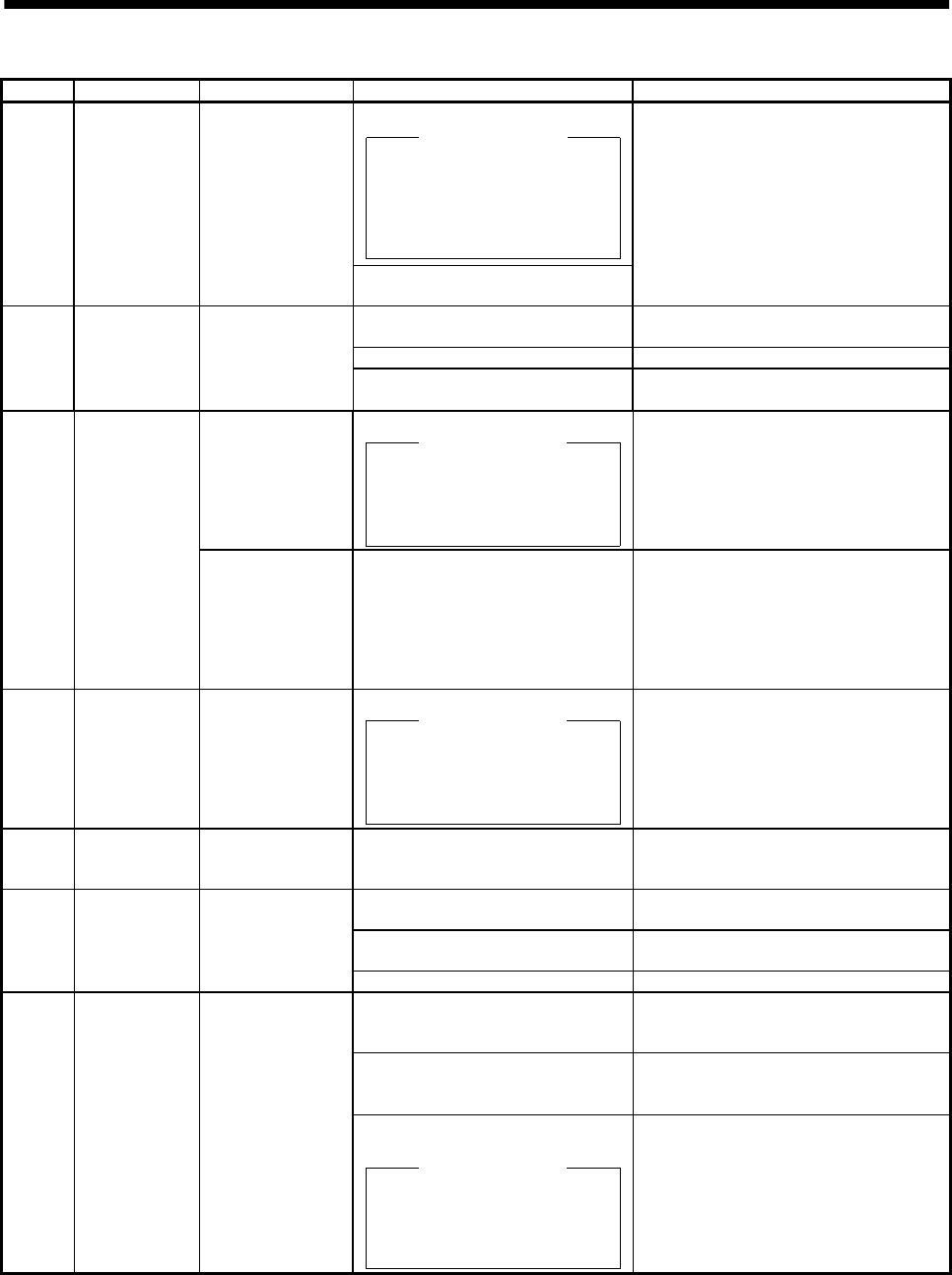
10. TROUBLESHOOTING
Display Name Definition Cause Action
1. Faulty parts in the servo amplifier
Checking method
Alarm (AL.15)
occurs if power is switched on
after disconnection of all cables
but the control circuit power
supply cables.
AL.15 Memory error 2 EEP-ROM fault
2. The number of write times to EEP-
ROM exceeded 100,000.
Change the servo amplifier.
1. Encoder connector (CN2)
disconnected.
Connect correctly.
2. Encoder fault Change the servo motor.
AL.16 Encoder error 1 Communication
error occurred
between encoder
and servo amplifier.
3. Encoder cable faulty
(Wire breakage or shorted)
Repair or change cable.
CPU/parts fault 1. Faulty parts in the servo amplifier.
Checking method
Alarm (AL.17) occurs if power is
switched on after disconnection
of all cable but the control circuit
power supply cable.
Change the servo amplifier.
AL.17 Board error 2
The output
terminals U, V, W of
the servo amplifier
and the input
terminals U, V, W of
the servo motor are
not connected.
2. The wiring of U, V, W is
disconnected or not connected.
Correctly connect the output terminals U,
V, W of the servo amplifier and the input
terminals U, V, W of the servo motor.
AL.19 Memory error 3 ROM memory fault Faulty parts in the servo amplifier.
Checking method
Alarm (AL.19) occurs if power is
switched on after disconnection
of all cable but the control circuit
power supply cable.
Change the servo amplifier.
AL.1A Motor
combination
error
Wrong combination
of servo anplifier
and servo motor.
Wrong combination of servo amplifier
and servo motor connected.
Use correct combination.
1. Encoder connector (CN2)
disconnected.
Connect correctly.
2. Encoder cable faulty
(Wire breakage or shorted)
Repair or change the cable.
AL.20 Encoder error 2 Communication
error occurred
between encoder
and servo amplifier.
3. Encoder fault Change the servo motor.
1. Power input wires and servo motor
output wires are in contact at
main circuit terminal block (TE1).
Connect correctly.
2. Sheathes of servo motor power
cables deteriorated, resulting in
ground fault.
Change the cable.
AL.24 Main circuit
error
Ground fault
occurred at the
servo motor outputs
(U,V and W phases)
of the servo
amplififer.
3. Main circuit of servo amplifier
failed.
Checking method
AL.24 occurs if the servo is
switched on after disconnecting
the U, V, W power cables from
the servo amplifier.
Change the servo amplifier.