
Instruction Manual
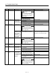
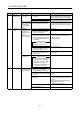
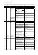
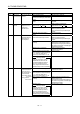
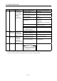
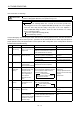
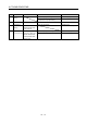
Table Of Contents
- Safety Instructions
- COMPLIANCE WITH EC DIRECTIVES
- CONFORMANCE WITH UL/C-UL STANDARD
- <
> - CONTENTS
- Optional Servo Motor Instruction Manual CONTENTS
- 1. FUNCTIONS AND CONFIGURATION
- 2. INSTALLATION
- 3. SIGNALS AND WIRING
- 3.1 Standard connection example
- 3.2 Internal connection diagram of servo amplifier
- 3.3 I/O signals
- 3.4 Detailed description of the signals
- 3.5 Alarm occurrence timing chart
- 3.6 Interfaces
- 3.7 Input power supply circuit
- 3.8 Connection of servo amplifier and servo motor
- 3.9 Servo motor with electromagnetic brake
- 3.10 Grounding
- 3.11 Servo amplifier terminal block (TE2) wiring method
- 3.12 Instructions for the 3M connector
- 3.13 Power line circuit of the MR-J2S-11KA to MR-J2S-22KA
- 4. OPERATION
- 5. PARAMETERS
- 6. DISPLAY AND OPERATION
- 7. GENERAL GAIN ADJUSTMENT
- 8. SPECIAL ADJUSTMENT FUNCTIONS
- 9. INSPECTION
- 10. TROUBLESHOOTING
- 11. OUTLINE DIMENSION DRAWINGS
- 12. CHARACTERISTICS
- 13. OPTIONS AND AUXILIARY EQUIPMENT
- 13.1 Options
- 13.1.1 Regenerative brake options
- 13.1.2 Brake unit
- 13.1.3 Power regeneration converter
- 13.1.4 External dynamic brake
- 13.1.5 Cables and connectors
- 13.1.6 Junction terminal block (MR-TB20)
- 13.1.7 Maintenance junction card (MR-J2CN3TM)
- 13.1.8 Battery (MR-BAT, A6BAT)
- 13.1.9 MR Configurator (Servo configurations software)
- 13.1.10 Power regeneration common converter
- 13.1.11 Heat sink outside mounting attachment (MR-JACN)
- 13.2 Auxiliary equipment
- 13.2.1 Recommended wires
- 13.2.2 No-fuse breakers, fuses, magnetic contactors
- 13.2.3 Power factor improving reactors
- 13.2.4 Power factor improving DC reactors
- 13.2.5 Relays
- 13.2.6 Surge absorbers
- 13.2.7 Noise reduction techniques
- 13.2.8 Leakage current breaker
- 13.2.9 EMC filter
- 13.2.10 Setting potentiometers for analog inputs
- 13.1 Options
- 14. COMMUNICATION FUNCTIONS
- 14.1 Configuration
- 14.2 Communication specifications
- 14.3 Protocol
- 14.4 Character codes
- 14.5 Error codes
- 14.6 Checksum
- 14.7 Time-out operation
- 14.8 Retry operation
- 14.9 Initialization
- 14.10 Communication procedure example
- 14.11 Command and data No. list
- 14.12 Detailed explanations of commands
- 14.12.1 Data processing
- 14.12.2 Status display
- 14.12.3 Parameter
- 14.12.4 External I/O pin statuses (DIO diagnosis)
- 14.12.5 Disable/enable of external I/O signals (DIO)
- 14.12.6 External input signal ON/OFF (test operation)
- 14.12.7 Test operation mode
- 14.12.8 Output signal pin ON/OFF output signal (DO) forced output
- 14.12.9 Alarm history
- 14.12.10 Current alarm
- 14.12.11 Other commands
- 15. ABSOLUTE POSITION DETECTION SYSTEM
- 15.1 Outline
- 15.2 Specifications
- 15.3 Battery installation procedure
- 15.4 Standard connection diagram
- 15.5 Signal explanation
- 15.6 Startup procedure
- 15.7 Absolute position data transfer protocol
- 15.8 Examples of use
- 15.9 Confirmation of absolute position detection data
- 15.10 Absolute position data transfer errors
- Appendix
- REVISIONS
10 - 11
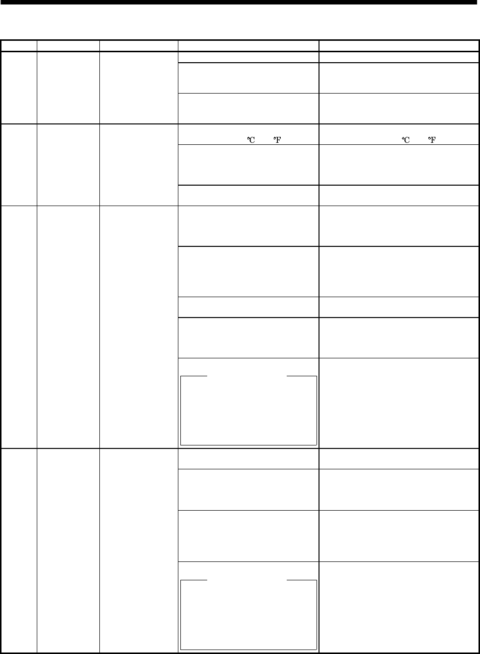
10. TROUBLESHOOTING
Display Name Definition Cause Action
1. Servo amplifier faulty. Change the servo amplifier.
2. The power supply was turned on
and off continuously by overloaded
status.
The drive method is reviewed.
AL.45 Main circuit
device overheat
Main circuit device
overheat
3. Air cooling fan of servo amplifier
stops.
1. Exchange the cooling fan or the servo
amplifier.
2. Reduce ambient temperature.
1. Ambient temperature of servo
motor is over 40
(104
).
Review environment so that ambient
temperature is 0 to 40
(104
).
2. Servo motor is overloaded. 1. Reduce load.
2. Review operation pattern.
3. Use servo motor that provides larger
output.
AL.46 Servo motor
overheat
Servo motor
temperature rise
actuated the
thermal sensor.
3. Thermal sensor in encoder is
faulty.
Change servo motor.
1. Servo amplifier is used in excess
of its continuous output current.
1. Reduce load.
2. Review operation pattern.
3. Use servo motor that provides larger
output.
2. Servo system is instable and
hunting.
1. Repeat acceleration/
deceleration to execute auto tuning.
2. Change auto tuning response setting.
3. Set auto tuning to OFF and make gain
adjustment manually.
3. Machine struck something. 1. Review operation pattern.
2. Install limit switches.
4. Wrong connection of servo motor.
Servo amplifier's output terminals
U, V, W do not match servo
motor's input terminals U, V, W.
Connect correctly.
AL.50 Overload 1 Load exceeded
overload protection
characteristic of
servo amplifier.
5. Encoder faulty.
Checking method
When the servo motor shaft is
rotated with the servo off, the
cumulative feedback pulses do
not vary in proportion to the
rotary angle of the shaft but the
indication skips or returns midway.
Change the servo motor.
1. Machine struck something. 1. Review operation pattern.
2. Install limit switches.
2. Wrong connection of servo motor.
Servo amplifier's output terminals
U, V, W do not match servo
motor's input terminals U, V, W.
Connect correctly.
3. Servo system is instable and
hunting.
1. Repeat acceleration/deceleration to
execute auto tuning.
2. Change auto tuning response setting.
3. Set auto tuning to OFF and make gain
adjustment manually.
AL.51 Overload 2 Machine collision or
the like caused max.
output current to
flow successively for
several seconds.
Servo motor locked:
1s or more
During rotation:
2.5s or more
4. Encoder faulty.
Checking method
When the servo motor shaft is
rotated with the servo off, the
cumulative feedback pulses do
not vary in proportion to the
rotary angle of the shaft but the
indication skips or returns midway.
Change the servo motor.