
Instruction Manual
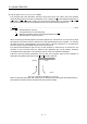
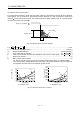


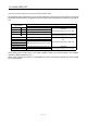

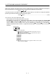
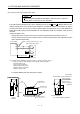
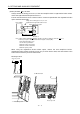
Table Of Contents
- Safety Instructions
- COMPLIANCE WITH EC DIRECTIVES
- CONFORMANCE WITH UL/C-UL STANDARD
- <
> - CONTENTS
- Optional Servo Motor Instruction Manual CONTENTS
- 1. FUNCTIONS AND CONFIGURATION
- 2. INSTALLATION
- 3. SIGNALS AND WIRING
- 3.1 Standard connection example
- 3.2 Internal connection diagram of servo amplifier
- 3.3 I/O signals
- 3.4 Detailed description of the signals
- 3.5 Alarm occurrence timing chart
- 3.6 Interfaces
- 3.7 Input power supply circuit
- 3.8 Connection of servo amplifier and servo motor
- 3.9 Servo motor with electromagnetic brake
- 3.10 Grounding
- 3.11 Servo amplifier terminal block (TE2) wiring method
- 3.12 Instructions for the 3M connector
- 3.13 Power line circuit of the MR-J2S-11KA to MR-J2S-22KA
- 4. OPERATION
- 5. PARAMETERS
- 6. DISPLAY AND OPERATION
- 7. GENERAL GAIN ADJUSTMENT
- 8. SPECIAL ADJUSTMENT FUNCTIONS
- 9. INSPECTION
- 10. TROUBLESHOOTING
- 11. OUTLINE DIMENSION DRAWINGS
- 12. CHARACTERISTICS
- 13. OPTIONS AND AUXILIARY EQUIPMENT
- 13.1 Options
- 13.1.1 Regenerative brake options
- 13.1.2 Brake unit
- 13.1.3 Power regeneration converter
- 13.1.4 External dynamic brake
- 13.1.5 Cables and connectors
- 13.1.6 Junction terminal block (MR-TB20)
- 13.1.7 Maintenance junction card (MR-J2CN3TM)
- 13.1.8 Battery (MR-BAT, A6BAT)
- 13.1.9 MR Configurator (Servo configurations software)
- 13.1.10 Power regeneration common converter
- 13.1.11 Heat sink outside mounting attachment (MR-JACN)
- 13.2 Auxiliary equipment
- 13.2.1 Recommended wires
- 13.2.2 No-fuse breakers, fuses, magnetic contactors
- 13.2.3 Power factor improving reactors
- 13.2.4 Power factor improving DC reactors
- 13.2.5 Relays
- 13.2.6 Surge absorbers
- 13.2.7 Noise reduction techniques
- 13.2.8 Leakage current breaker
- 13.2.9 EMC filter
- 13.2.10 Setting potentiometers for analog inputs
- 13.1 Options
- 14. COMMUNICATION FUNCTIONS
- 14.1 Configuration
- 14.2 Communication specifications
- 14.3 Protocol
- 14.4 Character codes
- 14.5 Error codes
- 14.6 Checksum
- 14.7 Time-out operation
- 14.8 Retry operation
- 14.9 Initialization
- 14.10 Communication procedure example
- 14.11 Command and data No. list
- 14.12 Detailed explanations of commands
- 14.12.1 Data processing
- 14.12.2 Status display
- 14.12.3 Parameter
- 14.12.4 External I/O pin statuses (DIO diagnosis)
- 14.12.5 Disable/enable of external I/O signals (DIO)
- 14.12.6 External input signal ON/OFF (test operation)
- 14.12.7 Test operation mode
- 14.12.8 Output signal pin ON/OFF output signal (DO) forced output
- 14.12.9 Alarm history
- 14.12.10 Current alarm
- 14.12.11 Other commands
- 15. ABSOLUTE POSITION DETECTION SYSTEM
- 15.1 Outline
- 15.2 Specifications
- 15.3 Battery installation procedure
- 15.4 Standard connection diagram
- 15.5 Signal explanation
- 15.6 Startup procedure
- 15.7 Absolute position data transfer protocol
- 15.8 Examples of use
- 15.9 Confirmation of absolute position detection data
- 15.10 Absolute position data transfer errors
- Appendix
- REVISIONS
12 - 6
12. CHARACTERISTICS
Time constant [s]
0.005
0.01
0.015
0.02
0.025
0.03
0.035
0.04
0
50 5000 1000
121
201
301
81
Speed [r/min]
Time constant [s]
Speed [r/min]
0
0.005
0.01
0.015
0.02
0.025
0.03
0.035
0.04
0.045
0 500 1000 1500 2000
352
202
702
102
152
502
52
c. HC-SFS1000r/min series d. HC-SFS2000r/min series
0
0.02
0.04
0.06
0.08
0.1
0.12
50 500 1000 1500 2000 2500 30000
203
353
53
103
153
Speed [r/min]
Time constant [s]
Speed [r/min]
Time constant [s]
0
0.002
0.004
0.006
0.008
0.01
0.012
0.014
0.016
0.018
0 500 1000 1500 2000 2500 3000
153
503
103
353
203
e. HC-SFS3000r/min series f. HC-RFS series
Time constant [s]
Speed [r/min]
352
500 1000 1500 20000
0
0.01
0.02
0.03
0.04
0.05
0.06
0.07
0.08
0.09
0.1
502
72
202
152
0
0.01
0.02
0.03
0.04
0.05
0.06
50 500 100015002000250030000
43
23
0.07
13
73
Speed [r/min]
Time constant [s]
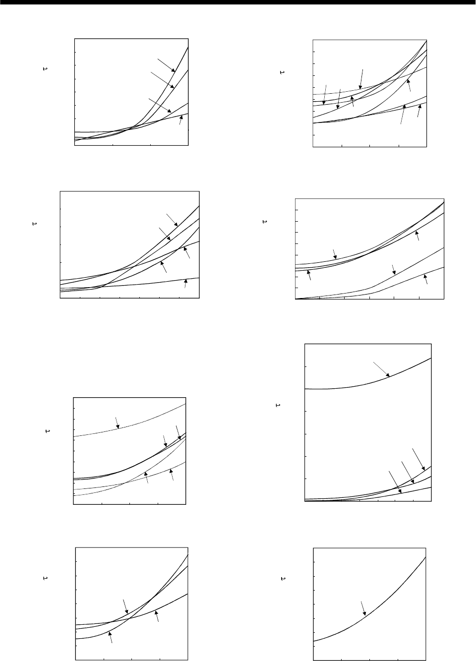
g. HC-UFS 2000r/min series h. HC-UFS3000r/min series
0
500 1000 1500 20000
0.04
0.035
0.03
0.025
0.02
0.015
0.01
0.005
11K2
22K2
15K2
Time constant [s]
Speed [r/min]
0
500 1000 1500 20000
40.0
35.0
30.0
25.0
20.0
15.0
10.0
5.0
302
Time constant [s]
Speed [r/min]
i. HA-LFS series j. HC-LFS series
Fig. 12.8 Dynamic brake time constant 2