
Instruction Manual
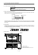
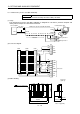
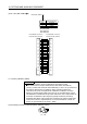
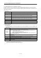
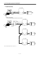
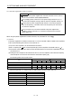
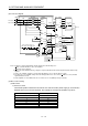
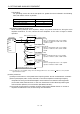
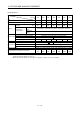
Table Of Contents
- Safety Instructions
- COMPLIANCE WITH EC DIRECTIVES
- CONFORMANCE WITH UL/C-UL STANDARD
- <
> - CONTENTS
- Optional Servo Motor Instruction Manual CONTENTS
- 1. FUNCTIONS AND CONFIGURATION
- 2. INSTALLATION
- 3. SIGNALS AND WIRING
- 3.1 Standard connection example
- 3.2 Internal connection diagram of servo amplifier
- 3.3 I/O signals
- 3.4 Detailed description of the signals
- 3.5 Alarm occurrence timing chart
- 3.6 Interfaces
- 3.7 Input power supply circuit
- 3.8 Connection of servo amplifier and servo motor
- 3.9 Servo motor with electromagnetic brake
- 3.10 Grounding
- 3.11 Servo amplifier terminal block (TE2) wiring method
- 3.12 Instructions for the 3M connector
- 3.13 Power line circuit of the MR-J2S-11KA to MR-J2S-22KA
- 4. OPERATION
- 5. PARAMETERS
- 6. DISPLAY AND OPERATION
- 7. GENERAL GAIN ADJUSTMENT
- 8. SPECIAL ADJUSTMENT FUNCTIONS
- 9. INSPECTION
- 10. TROUBLESHOOTING
- 11. OUTLINE DIMENSION DRAWINGS
- 12. CHARACTERISTICS
- 13. OPTIONS AND AUXILIARY EQUIPMENT
- 13.1 Options
- 13.1.1 Regenerative brake options
- 13.1.2 Brake unit
- 13.1.3 Power regeneration converter
- 13.1.4 External dynamic brake
- 13.1.5 Cables and connectors
- 13.1.6 Junction terminal block (MR-TB20)
- 13.1.7 Maintenance junction card (MR-J2CN3TM)
- 13.1.8 Battery (MR-BAT, A6BAT)
- 13.1.9 MR Configurator (Servo configurations software)
- 13.1.10 Power regeneration common converter
- 13.1.11 Heat sink outside mounting attachment (MR-JACN)
- 13.2 Auxiliary equipment
- 13.2.1 Recommended wires
- 13.2.2 No-fuse breakers, fuses, magnetic contactors
- 13.2.3 Power factor improving reactors
- 13.2.4 Power factor improving DC reactors
- 13.2.5 Relays
- 13.2.6 Surge absorbers
- 13.2.7 Noise reduction techniques
- 13.2.8 Leakage current breaker
- 13.2.9 EMC filter
- 13.2.10 Setting potentiometers for analog inputs
- 13.1 Options
- 14. COMMUNICATION FUNCTIONS
- 14.1 Configuration
- 14.2 Communication specifications
- 14.3 Protocol
- 14.4 Character codes
- 14.5 Error codes
- 14.6 Checksum
- 14.7 Time-out operation
- 14.8 Retry operation
- 14.9 Initialization
- 14.10 Communication procedure example
- 14.11 Command and data No. list
- 14.12 Detailed explanations of commands
- 14.12.1 Data processing
- 14.12.2 Status display
- 14.12.3 Parameter
- 14.12.4 External I/O pin statuses (DIO diagnosis)
- 14.12.5 Disable/enable of external I/O signals (DIO)
- 14.12.6 External input signal ON/OFF (test operation)
- 14.12.7 Test operation mode
- 14.12.8 Output signal pin ON/OFF output signal (DO) forced output
- 14.12.9 Alarm history
- 14.12.10 Current alarm
- 14.12.11 Other commands
- 15. ABSOLUTE POSITION DETECTION SYSTEM
- 15.1 Outline
- 15.2 Specifications
- 15.3 Battery installation procedure
- 15.4 Standard connection diagram
- 15.5 Signal explanation
- 15.6 Startup procedure
- 15.7 Absolute position data transfer protocol
- 15.8 Examples of use
- 15.9 Confirmation of absolute position detection data
- 15.10 Absolute position data transfer errors
- Appendix
- REVISIONS

13 - 30
13. OPTIONS AND AUXILIARY EQUIPMENT
13.1.9 MR Configurator (Servo configurations software)
The MR Configurator (servo configuration software MRZJW3-SETUP151E) uses the communication
function of the servo amplifier to perform parameter setting changes, graph display, test operation, etc.
on a personal computer.
(1) Specifications
Item Description
Communication signal Conforms to RS-232C.
Baudrate [bps] 57600, 38400, 19200, 9600
Monitor
Display, high speed monitor, trend graph
Minimum resolution changes with the processing speed of the personal computer.
Alarm Display, history, amplifier data
Diagnostic
Digital I/O, no motor rotation, total power-on time, amplifier version info, motor information,
tuning data, absolute encoder data, automatic voltage control, Axis name setting.
Parameters Parameter list, turning, change list, detailed information
Test operation Jog operation, positioning operation, motor-less operation, Do forced output, program operation.
Advanced function Machine analyzer, gain search, machine simulation.
File operation Data read, save, print
Others Automatic demo, help display
(2) System configuration
(a) Components
To use this software, the following components are required in addition to the servo amplifier and
servo motor:
Model (Note 1) Description
(Note 2)
Personal
computer
IBM PC-AT compatible where the English version of Windows
®
95, Windows
®
98, Windows
®
Me,
Windows NT
®
Workstation 4.0 or Windows
®
2000 Professional operates
Processor: Pentium
®
133MHz or more (Windows
®
95, Windows
®
98, Windows NT
®
Workstation 4.0,
Windows
®
2000 Professional)
Pentium
®
150MHz or more (Windows
®
Me)
Memory: 16MB or more (Windows
®
95), 24MB or more (Windows
®
98)
32MB or more (Windows
®
Me, Windows NT
®
Workstation 4.0, Windows
®
2000 Professional)
Free hard disk space: 30MB or more
Serial port used
OS
Windows
®
95, Windows
®
98, Windows
®
Me, Windows NT
®
Workstation 4.0, Windows
®
2000 Professional
(English version)
Display
One whose resolution is 800
600 or more and that can provide a high color (16 bit) display.
Connectable with the above personal computer.
Keyboard Connectable with the above personal computer.
Mouse Connectable with the above personal computer. Note that a serial mouse is not used.
Printer Connectable with the above personal computer.
Communication
cable
MR-CPCATCBL3M
When this cannot be used, refer to (3) Section 12.1.5 and fabricate.
Note 1. Windows and Windows NT are the registered trademarks of Microsoft Corporation in the United State and other countries.
Pentium is the registered trademarks of Intel Corporation.
2. On some personal computers, this software may not run properly.