
Instruction Manual
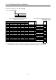
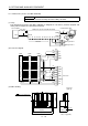
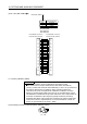
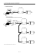
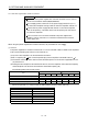
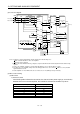
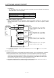
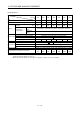
Table Of Contents
- Safety Instructions
- COMPLIANCE WITH EC DIRECTIVES
- CONFORMANCE WITH UL/C-UL STANDARD
- <
> - CONTENTS
- Optional Servo Motor Instruction Manual CONTENTS
- 1. FUNCTIONS AND CONFIGURATION
- 2. INSTALLATION
- 3. SIGNALS AND WIRING
- 3.1 Standard connection example
- 3.2 Internal connection diagram of servo amplifier
- 3.3 I/O signals
- 3.4 Detailed description of the signals
- 3.5 Alarm occurrence timing chart
- 3.6 Interfaces
- 3.7 Input power supply circuit
- 3.8 Connection of servo amplifier and servo motor
- 3.9 Servo motor with electromagnetic brake
- 3.10 Grounding
- 3.11 Servo amplifier terminal block (TE2) wiring method
- 3.12 Instructions for the 3M connector
- 3.13 Power line circuit of the MR-J2S-11KA to MR-J2S-22KA
- 4. OPERATION
- 5. PARAMETERS
- 6. DISPLAY AND OPERATION
- 7. GENERAL GAIN ADJUSTMENT
- 8. SPECIAL ADJUSTMENT FUNCTIONS
- 9. INSPECTION
- 10. TROUBLESHOOTING
- 11. OUTLINE DIMENSION DRAWINGS
- 12. CHARACTERISTICS
- 13. OPTIONS AND AUXILIARY EQUIPMENT
- 13.1 Options
- 13.1.1 Regenerative brake options
- 13.1.2 Brake unit
- 13.1.3 Power regeneration converter
- 13.1.4 External dynamic brake
- 13.1.5 Cables and connectors
- 13.1.6 Junction terminal block (MR-TB20)
- 13.1.7 Maintenance junction card (MR-J2CN3TM)
- 13.1.8 Battery (MR-BAT, A6BAT)
- 13.1.9 MR Configurator (Servo configurations software)
- 13.1.10 Power regeneration common converter
- 13.1.11 Heat sink outside mounting attachment (MR-JACN)
- 13.2 Auxiliary equipment
- 13.2.1 Recommended wires
- 13.2.2 No-fuse breakers, fuses, magnetic contactors
- 13.2.3 Power factor improving reactors
- 13.2.4 Power factor improving DC reactors
- 13.2.5 Relays
- 13.2.6 Surge absorbers
- 13.2.7 Noise reduction techniques
- 13.2.8 Leakage current breaker
- 13.2.9 EMC filter
- 13.2.10 Setting potentiometers for analog inputs
- 13.1 Options
- 14. COMMUNICATION FUNCTIONS
- 14.1 Configuration
- 14.2 Communication specifications
- 14.3 Protocol
- 14.4 Character codes
- 14.5 Error codes
- 14.6 Checksum
- 14.7 Time-out operation
- 14.8 Retry operation
- 14.9 Initialization
- 14.10 Communication procedure example
- 14.11 Command and data No. list
- 14.12 Detailed explanations of commands
- 14.12.1 Data processing
- 14.12.2 Status display
- 14.12.3 Parameter
- 14.12.4 External I/O pin statuses (DIO diagnosis)
- 14.12.5 Disable/enable of external I/O signals (DIO)
- 14.12.6 External input signal ON/OFF (test operation)
- 14.12.7 Test operation mode
- 14.12.8 Output signal pin ON/OFF output signal (DO) forced output
- 14.12.9 Alarm history
- 14.12.10 Current alarm
- 14.12.11 Other commands
- 15. ABSOLUTE POSITION DETECTION SYSTEM
- 15.1 Outline
- 15.2 Specifications
- 15.3 Battery installation procedure
- 15.4 Standard connection diagram
- 15.5 Signal explanation
- 15.6 Startup procedure
- 15.7 Absolute position data transfer protocol
- 15.8 Examples of use
- 15.9 Confirmation of absolute position detection data
- 15.10 Absolute position data transfer errors
- Appendix
- REVISIONS

13 - 33
13. OPTIONS AND AUXILIARY EQUIPMENT
(2) Connection diagram
RA2
EMG
SON
C
B
R/L11
Three-phase
200 to 230VAC
S/L21
T/L
31
R2/L1
S2/L22
R2/L12
T2/L
32
S2/L2
(Note 3)
SG
P24
SD
RDYB
RDYA
RSO
SE
A
T2/L3
R/L11
S/L21
T/MC1
RES
SD
(Note
1)
L11
RES
SG
SG
ALM
VIN
U
V
W
SG
(Note 1)
(Note1)
(Note 3)
RA1
EMG
SON
(Note 2)
RA3
RA2
RA1
RA4
24VDC
power
supply
U
V
W
Thermel
relay
OHS2
OHS1
CN2
MC
NFB
FR-CVL FR-CV
MC
RA2 RA3 RA4
EMG
OFF
ON
RESET
SK
MC
(Note 2)
(Note 1)
Servo motor
Servo amplifier
(Note 1)
N
L21
P
P/L
P/L
P
1
(Note 5)
(Note 4)
Note 1. Configure a sequence that will shut off main circuit power in the following cases:
Alarm occurred in the FR-CV or the servo amplifier.
Emergency stop is activated.
2. For the servo motor with thermal relay, configure a sequence that will shut off main circuit power when the thermal relay
operates.
3. For the servo amplifier, configure a sequence that will switch the servo on after the FR-CV is ready.
4. For 7kW or less servo amplifier, always remove the wiring (3.5kW or less: across P-D, 5k
7kW: across P-C) of built-in
regenerative brake resistor.
5. For the amplifiers of 11k to 22kW, make sure to connect across P-P1. (Wiring is factory-connected.)
(3) Wires used for wiring
(a) Wire sizes
1) Across P-P, N-N
The following table indicates the connection wire sizes of the DC power supply (P, N terminals)
between the FR-CV and servo amplifier. The used wires are based on the 600V vinyl wires.
Total of servo amplifier capacities [kW] Wires[mm
2
]
1 or less 2
23.5
55.5
78
11 14
15 22
22 50