
Instruction Manual
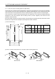
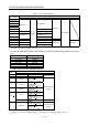
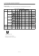
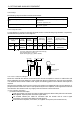
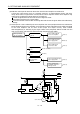
Table Of Contents
- Safety Instructions
- COMPLIANCE WITH EC DIRECTIVES
- CONFORMANCE WITH UL/C-UL STANDARD
- <
> - CONTENTS
- Optional Servo Motor Instruction Manual CONTENTS
- 1. FUNCTIONS AND CONFIGURATION
- 2. INSTALLATION
- 3. SIGNALS AND WIRING
- 3.1 Standard connection example
- 3.2 Internal connection diagram of servo amplifier
- 3.3 I/O signals
- 3.4 Detailed description of the signals
- 3.5 Alarm occurrence timing chart
- 3.6 Interfaces
- 3.7 Input power supply circuit
- 3.8 Connection of servo amplifier and servo motor
- 3.9 Servo motor with electromagnetic brake
- 3.10 Grounding
- 3.11 Servo amplifier terminal block (TE2) wiring method
- 3.12 Instructions for the 3M connector
- 3.13 Power line circuit of the MR-J2S-11KA to MR-J2S-22KA
- 4. OPERATION
- 5. PARAMETERS
- 6. DISPLAY AND OPERATION
- 7. GENERAL GAIN ADJUSTMENT
- 8. SPECIAL ADJUSTMENT FUNCTIONS
- 9. INSPECTION
- 10. TROUBLESHOOTING
- 11. OUTLINE DIMENSION DRAWINGS
- 12. CHARACTERISTICS
- 13. OPTIONS AND AUXILIARY EQUIPMENT
- 13.1 Options
- 13.1.1 Regenerative brake options
- 13.1.2 Brake unit
- 13.1.3 Power regeneration converter
- 13.1.4 External dynamic brake
- 13.1.5 Cables and connectors
- 13.1.6 Junction terminal block (MR-TB20)
- 13.1.7 Maintenance junction card (MR-J2CN3TM)
- 13.1.8 Battery (MR-BAT, A6BAT)
- 13.1.9 MR Configurator (Servo configurations software)
- 13.1.10 Power regeneration common converter
- 13.1.11 Heat sink outside mounting attachment (MR-JACN)
- 13.2 Auxiliary equipment
- 13.2.1 Recommended wires
- 13.2.2 No-fuse breakers, fuses, magnetic contactors
- 13.2.3 Power factor improving reactors
- 13.2.4 Power factor improving DC reactors
- 13.2.5 Relays
- 13.2.6 Surge absorbers
- 13.2.7 Noise reduction techniques
- 13.2.8 Leakage current breaker
- 13.2.9 EMC filter
- 13.2.10 Setting potentiometers for analog inputs
- 13.1 Options
- 14. COMMUNICATION FUNCTIONS
- 14.1 Configuration
- 14.2 Communication specifications
- 14.3 Protocol
- 14.4 Character codes
- 14.5 Error codes
- 14.6 Checksum
- 14.7 Time-out operation
- 14.8 Retry operation
- 14.9 Initialization
- 14.10 Communication procedure example
- 14.11 Command and data No. list
- 14.12 Detailed explanations of commands
- 14.12.1 Data processing
- 14.12.2 Status display
- 14.12.3 Parameter
- 14.12.4 External I/O pin statuses (DIO diagnosis)
- 14.12.5 Disable/enable of external I/O signals (DIO)
- 14.12.6 External input signal ON/OFF (test operation)
- 14.12.7 Test operation mode
- 14.12.8 Output signal pin ON/OFF output signal (DO) forced output
- 14.12.9 Alarm history
- 14.12.10 Current alarm
- 14.12.11 Other commands
- 15. ABSOLUTE POSITION DETECTION SYSTEM
- 15.1 Outline
- 15.2 Specifications
- 15.3 Battery installation procedure
- 15.4 Standard connection diagram
- 15.5 Signal explanation
- 15.6 Startup procedure
- 15.7 Absolute position data transfer protocol
- 15.8 Examples of use
- 15.9 Confirmation of absolute position detection data
- 15.10 Absolute position data transfer errors
- Appendix
- REVISIONS
13 - 41
13. OPTIONS AND AUXILIARY EQUIPMENT
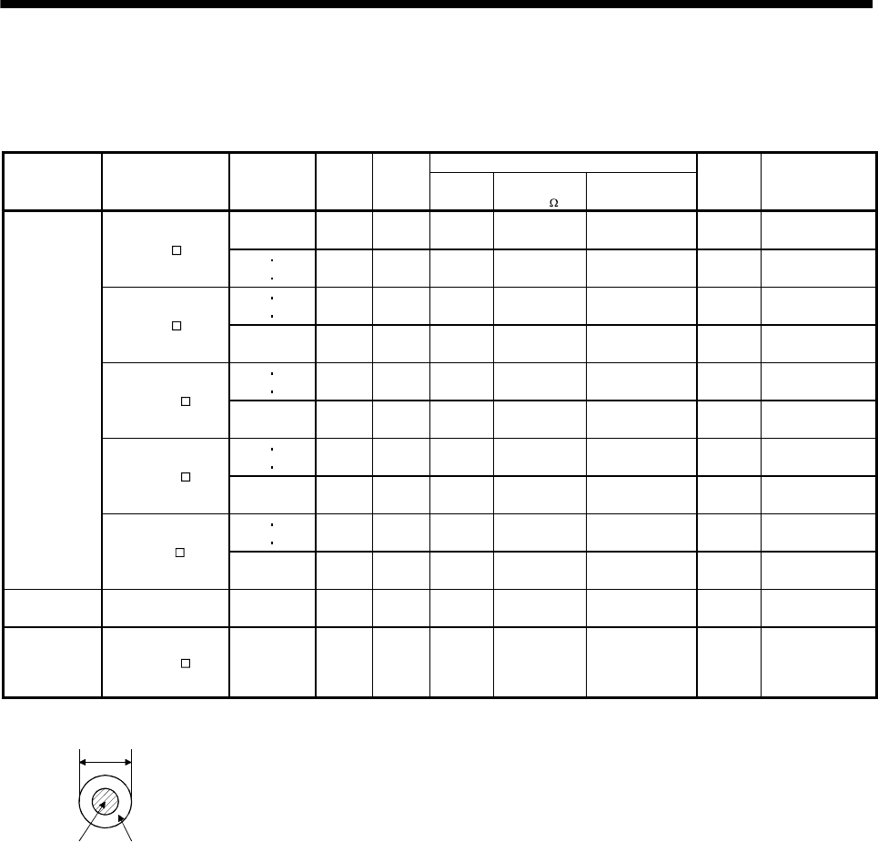
(2) Wires for cables
When fabricating a cable, use the wire models given in the following table or equivalent:
Table 13.3 Wires for option cables
Characteristics of one core
Type Model
Length
[m(ft)]
Core size
[mm
2
]
Number
of Cores
Structure
[Wires/mm]
Conductor
resistance[ /mm]
Insulation coating
ODd[mm] (Note 1)
(Note 3)
Finishing
OD [mm]
Wire model
2 to 10
(6.56 to 32.8)
0.08
12
(6 pairs)
7/0.127 222 0.38 5.6
UL20276 AWG#28
6pair (BLAC)
MR-JCCBL M-L
20
30
(65.6
98.4)
0.3
12
(6 pairs)
12/0.18 62 1.2 8.2
UL20276 AWG#22
6pair (BLAC)
2 5
(6.56
16.4)
0.2
12
(6 pairs)
40/0.08 105 0.88 7.2
(Note 2)
A14B2343 6P
MR-JCCBL M-H
10 to 50
(32.8 to 164)
0.2
14
(7 pairs)
40/0.08 105 0.88 8.0
(Note 2)
A14B0238 7P
2 5
(6.56
16.4)
0.08
8
(4 pairs)
7/0.127 222 0.38 4.7
UL20276 AWG#28
4pair (BLAC)
MR-JHSCBL M-L
10 to 30
(32.8 to 98.4)
0.3
12
(6 pairs)
12/0.18 62 1.2 8.2
UL20276 AWG#22
6pair (BLAC)
2 5
(6.56
16.4)
0.2
8
(4 pairs)
40/0.08 105 0.88 6.5
(Note 2)
A14B2339 4P
MR-JHSCBL M-H
10 to 50
(32.8 to 164)
0.2
12
(6 pairs)
40/0.08 105 0.88 7.2
(Note 2)
A14B2343 6P
2 5
(6.56
16.4)
0.2
8
(4 pairs)
40/0.08 105 0.88 6.5
(Note 2)
A14B2339 4P
Encoder cable
MR-ENCBL
M-H
10 to 50
(32.8 to 164)
0.2
12
(6 pairs)
40/0.08 105 0.88 7.2
(Note 2)
A14B2343 6P
Communication
cable
MR-CPCATCBL3M 3 (9.84) 0.08
6
(3 pairs)
7/0.127 222 0.38 4.6
UL20276 AWG#28
3pair (BLAC)
Bus cable MR-J2HBUS M
0.5 to 5
(1.64 to 16.4)
0.08
20
(10 pairs)
7/0.127 222 0.38 6.1
UL20276 AWG#28
10pair (CREAM)
Note 1. d is as shown below:
d
Conductor Insulation sheath
2. Purchased from Toa Electric Industry
3. Standard OD. Max. OD is about 10% greater.