
Instruction Manual
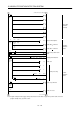
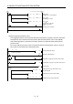
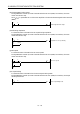

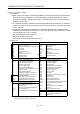
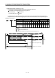
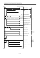
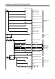
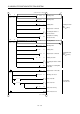
Table Of Contents
- Safety Instructions
- COMPLIANCE WITH EC DIRECTIVES
- CONFORMANCE WITH UL/C-UL STANDARD
- <
> - CONTENTS
- Optional Servo Motor Instruction Manual CONTENTS
- 1. FUNCTIONS AND CONFIGURATION
- 2. INSTALLATION
- 3. SIGNALS AND WIRING
- 3.1 Standard connection example
- 3.2 Internal connection diagram of servo amplifier
- 3.3 I/O signals
- 3.4 Detailed description of the signals
- 3.5 Alarm occurrence timing chart
- 3.6 Interfaces
- 3.7 Input power supply circuit
- 3.8 Connection of servo amplifier and servo motor
- 3.9 Servo motor with electromagnetic brake
- 3.10 Grounding
- 3.11 Servo amplifier terminal block (TE2) wiring method
- 3.12 Instructions for the 3M connector
- 3.13 Power line circuit of the MR-J2S-11KA to MR-J2S-22KA
- 4. OPERATION
- 5. PARAMETERS
- 6. DISPLAY AND OPERATION
- 7. GENERAL GAIN ADJUSTMENT
- 8. SPECIAL ADJUSTMENT FUNCTIONS
- 9. INSPECTION
- 10. TROUBLESHOOTING
- 11. OUTLINE DIMENSION DRAWINGS
- 12. CHARACTERISTICS
- 13. OPTIONS AND AUXILIARY EQUIPMENT
- 13.1 Options
- 13.1.1 Regenerative brake options
- 13.1.2 Brake unit
- 13.1.3 Power regeneration converter
- 13.1.4 External dynamic brake
- 13.1.5 Cables and connectors
- 13.1.6 Junction terminal block (MR-TB20)
- 13.1.7 Maintenance junction card (MR-J2CN3TM)
- 13.1.8 Battery (MR-BAT, A6BAT)
- 13.1.9 MR Configurator (Servo configurations software)
- 13.1.10 Power regeneration common converter
- 13.1.11 Heat sink outside mounting attachment (MR-JACN)
- 13.2 Auxiliary equipment
- 13.2.1 Recommended wires
- 13.2.2 No-fuse breakers, fuses, magnetic contactors
- 13.2.3 Power factor improving reactors
- 13.2.4 Power factor improving DC reactors
- 13.2.5 Relays
- 13.2.6 Surge absorbers
- 13.2.7 Noise reduction techniques
- 13.2.8 Leakage current breaker
- 13.2.9 EMC filter
- 13.2.10 Setting potentiometers for analog inputs
- 13.1 Options
- 14. COMMUNICATION FUNCTIONS
- 14.1 Configuration
- 14.2 Communication specifications
- 14.3 Protocol
- 14.4 Character codes
- 14.5 Error codes
- 14.6 Checksum
- 14.7 Time-out operation
- 14.8 Retry operation
- 14.9 Initialization
- 14.10 Communication procedure example
- 14.11 Command and data No. list
- 14.12 Detailed explanations of commands
- 14.12.1 Data processing
- 14.12.2 Status display
- 14.12.3 Parameter
- 14.12.4 External I/O pin statuses (DIO diagnosis)
- 14.12.5 Disable/enable of external I/O signals (DIO)
- 14.12.6 External input signal ON/OFF (test operation)
- 14.12.7 Test operation mode
- 14.12.8 Output signal pin ON/OFF output signal (DO) forced output
- 14.12.9 Alarm history
- 14.12.10 Current alarm
- 14.12.11 Other commands
- 15. ABSOLUTE POSITION DETECTION SYSTEM
- 15.1 Outline
- 15.2 Specifications
- 15.3 Battery installation procedure
- 15.4 Standard connection diagram
- 15.5 Signal explanation
- 15.6 Startup procedure
- 15.7 Absolute position data transfer protocol
- 15.8 Examples of use
- 15.9 Confirmation of absolute position detection data
- 15.10 Absolute position data transfer errors
- Appendix
- REVISIONS
15 - 45
15. ABSOLUTE POSITION DETECTION SYSTEM
M8000
K1K4M100K25K0TO
M200
K1K3M200K28K0FROM
K1D106K26K0DFROM
M108RST
END
6 6
FX2 1PG
Transmission of control signals
1PG FX2
Transmission of status
1PG FX2
Transmission of present
position D106, D107
1PG
Resetting start command
(Continued from preceding page)
Normally
ON
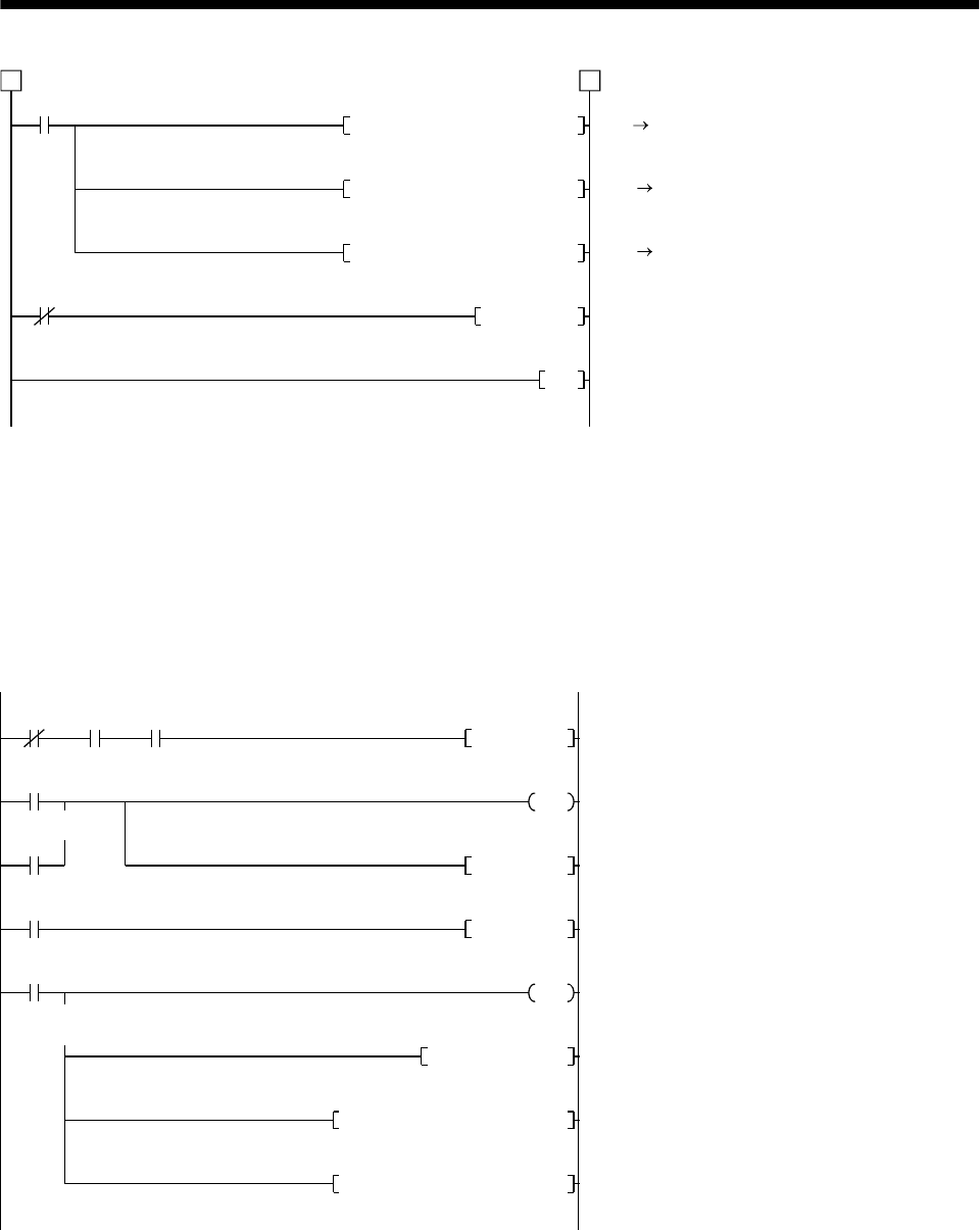
(d) Data set type home position return
After jogging the machine to the position where the home position (e.g.500) is to be set, choose the
home position return mode set the home position with the home position return start (PBON).
After switching power on, rotate the servo motor more than 1 revolution before starting home
position return.
Do not turn ON the clear (CR) (Y5) for an operation other than home position return. Turning it
ON in other circumstances will cause position shift.
Y1 X0 X14
M70
M71
T210
M70PLS
M71
D24K500DMOVP
K1D24K13K0DTOP
K1D24K26K0DTOP
T210
M71SET
K10
M71RST
Y5
Clear (CR) ON timer request
Clear (CR) 100ms ON timer
Setting data set type home position return request
Resetting data set type home position return reques
t
Clear (CR) ON
Setting X-axis home position address "500"
in the data register
Changing X-axis home position address
Changing X-axis present position data
ABS transfer
mode
Positioning
completion
Home position
return start PB
Clear signal ON
timer request
Date set type home position return request
Clear signal 100ms ON timer
Data set type
home position
return request