
Instruction Manual
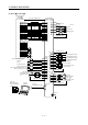
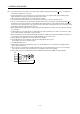
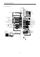

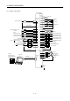
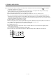
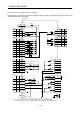
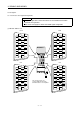
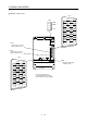
Table Of Contents
- Safety Instructions
- COMPLIANCE WITH EC DIRECTIVES
- CONFORMANCE WITH UL/C-UL STANDARD
- <
> - CONTENTS
- Optional Servo Motor Instruction Manual CONTENTS
- 1. FUNCTIONS AND CONFIGURATION
- 2. INSTALLATION
- 3. SIGNALS AND WIRING
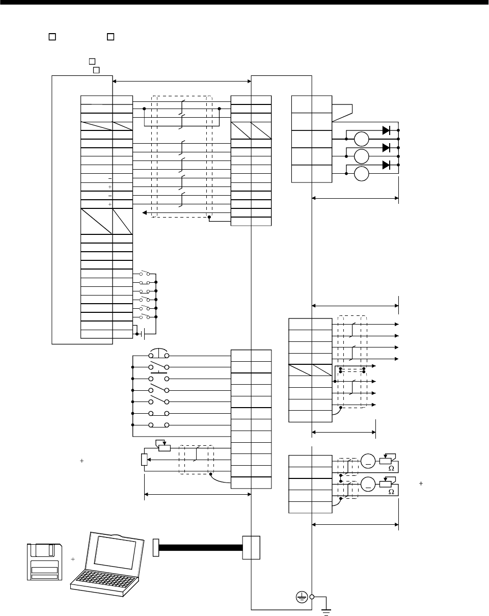
- 3.1 Standard connection example
- 3.2 Internal connection diagram of servo amplifier
- 3.3 I/O signals
- 3.4 Detailed description of the signals
- 3.5 Alarm occurrence timing chart
- 3.6 Interfaces
- 3.7 Input power supply circuit
- 3.8 Connection of servo amplifier and servo motor
- 3.9 Servo motor with electromagnetic brake
- 3.10 Grounding
- 3.11 Servo amplifier terminal block (TE2) wiring method
- 3.12 Instructions for the 3M connector
- 3.13 Power line circuit of the MR-J2S-11KA to MR-J2S-22KA
- 4. OPERATION
- 5. PARAMETERS
- 6. DISPLAY AND OPERATION
- 7. GENERAL GAIN ADJUSTMENT
- 8. SPECIAL ADJUSTMENT FUNCTIONS
- 9. INSPECTION
- 10. TROUBLESHOOTING
- 11. OUTLINE DIMENSION DRAWINGS
- 12. CHARACTERISTICS
- 13. OPTIONS AND AUXILIARY EQUIPMENT
- 13.1 Options
- 13.1.1 Regenerative brake options
- 13.1.2 Brake unit
- 13.1.3 Power regeneration converter
- 13.1.4 External dynamic brake
- 13.1.5 Cables and connectors
- 13.1.6 Junction terminal block (MR-TB20)
- 13.1.7 Maintenance junction card (MR-J2CN3TM)
- 13.1.8 Battery (MR-BAT, A6BAT)
- 13.1.9 MR Configurator (Servo configurations software)
- 13.1.10 Power regeneration common converter
- 13.1.11 Heat sink outside mounting attachment (MR-JACN)
- 13.2 Auxiliary equipment
- 13.2.1 Recommended wires
- 13.2.2 No-fuse breakers, fuses, magnetic contactors
- 13.2.3 Power factor improving reactors
- 13.2.4 Power factor improving DC reactors
- 13.2.5 Relays
- 13.2.6 Surge absorbers
- 13.2.7 Noise reduction techniques
- 13.2.8 Leakage current breaker
- 13.2.9 EMC filter
- 13.2.10 Setting potentiometers for analog inputs
- 13.1 Options
- 14. COMMUNICATION FUNCTIONS
- 14.1 Configuration
- 14.2 Communication specifications
- 14.3 Protocol
- 14.4 Character codes
- 14.5 Error codes
- 14.6 Checksum
- 14.7 Time-out operation
- 14.8 Retry operation
- 14.9 Initialization
- 14.10 Communication procedure example
- 14.11 Command and data No. list
- 14.12 Detailed explanations of commands
- 14.12.1 Data processing
- 14.12.2 Status display
- 14.12.3 Parameter
- 14.12.4 External I/O pin statuses (DIO diagnosis)
- 14.12.5 Disable/enable of external I/O signals (DIO)
- 14.12.6 External input signal ON/OFF (test operation)
- 14.12.7 Test operation mode
- 14.12.8 Output signal pin ON/OFF output signal (DO) forced output
- 14.12.9 Alarm history
- 14.12.10 Current alarm
- 14.12.11 Other commands
- 15. ABSOLUTE POSITION DETECTION SYSTEM
- 15.1 Outline
- 15.2 Specifications
- 15.3 Battery installation procedure
- 15.4 Standard connection diagram
- 15.5 Signal explanation
- 15.6 Startup procedure
- 15.7 Absolute position data transfer protocol
- 15.8 Examples of use
- 15.9 Confirmation of absolute position detection data
- 15.10 Absolute position data transfer errors
- Appendix
- REVISIONS
3 - 4
3. SIGNALS AND WIRING
(2) AD75P (A1SD75P )
VDD
RA1
RA2
RA3
18
15
5
14
8
9
16
17
1
11
EMG
SON
RES
PC
TL
LSP
LSN
SD
SG
P15R
LG
10
12
ALM
19 ZSP
6TLC
14
7
16
17
4
LA
LAR
LB
LBR
LG
OP
P15R
SD
1
6
CN1B
CN3
13 COM
3
TLA
(Note 4,9)
CN1A
4
13
3
SD
LG
14
MO1
LG
MO2
CN3
A
A
COM
INP
LZ
CR
PG
NP
NG
RD
SG
PP
LZR
SD
LG
1
26
8
24
5
21
4
22
7
23
3
25
6
1
20
12
14
35
16
DOG
COM
RLS
START
CHG
FLS
13
15
11
STOP
COM
2
36
19
DC24V
Positioning module
AD75P
(A1SD75P )
Ready
COM
INPS
PGO(24V)
PGO(5V)
PGO COM
CLEAR
CLEAR COM
PULSE F
PULSE F
PULSE R
PULSE R
PULSE F
PULSE R
(Note 10) 10m(32ft) max.
Servo amplifier
(Note 4,9)
CN1A
(Note 4)
CN1B
(Note 12)
(Note 7)
(Note 2,5)
Trouble
Zero speed
Limiting torque
Encoder A-phase pulse
(differential line driver)
Encoder B-phase pulse
(differential line driver)
Control common
Encoder Z-phase pulse
(open collector)
(Note 4,9)
(Note 4,9,14)
Plate
Plate
(Note 3, 6) Emergency stop
Servo-on
Reset
Proportion control
Torque limit selection
(Note 6) Forward rotation stroke end
Reverse rotation stroke end
Upper limit setting
Analog torque limit
10V/max. torque
(Note 11)
MR Configurator
(Servo configuration
software)
Personal
computer
(Note 8)
Communication cable
(Note 1)
(Note 8)
Analog monitor
Max. 1mA
Reading in both
directions
2m(6.5ft) max.
10k
10k
Plate
19
9
18
5
15
2
10
12
3
8
13
Plate
(Note 4,9)
2m(6.5ft) max.
(Note 13)
PULSE COM
PULSE COM
2m(6.5ft) or less
10m(32ft) or less
10m(32ft) or less
Control common