
Instruction Manual
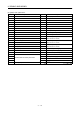
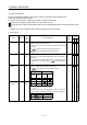
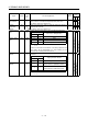
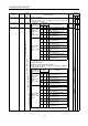
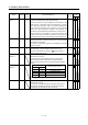
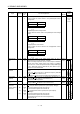
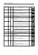
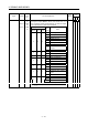
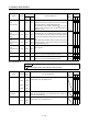

Table Of Contents
- Safety Instructions
- COMPLIANCE WITH EC DIRECTIVES
- CONFORMANCE WITH UL/C-UL STANDARD
- <
> - CONTENTS
- Optional Servo Motor Instruction Manual CONTENTS
- 1. FUNCTIONS AND CONFIGURATION
- 2. INSTALLATION
- 3. SIGNALS AND WIRING
- 3.1 Standard connection example
- 3.2 Internal connection diagram of servo amplifier
- 3.3 I/O signals
- 3.4 Detailed description of the signals
- 3.5 Alarm occurrence timing chart
- 3.6 Interfaces
- 3.7 Input power supply circuit
- 3.8 Connection of servo amplifier and servo motor
- 3.9 Servo motor with electromagnetic brake
- 3.10 Grounding
- 3.11 Servo amplifier terminal block (TE2) wiring method
- 3.12 Instructions for the 3M connector
- 3.13 Power line circuit of the MR-J2S-11KA to MR-J2S-22KA
- 4. OPERATION
- 5. PARAMETERS
- 6. DISPLAY AND OPERATION
- 7. GENERAL GAIN ADJUSTMENT
- 8. SPECIAL ADJUSTMENT FUNCTIONS
- 9. INSPECTION
- 10. TROUBLESHOOTING
- 11. OUTLINE DIMENSION DRAWINGS
- 12. CHARACTERISTICS
- 13. OPTIONS AND AUXILIARY EQUIPMENT
- 13.1 Options
- 13.1.1 Regenerative brake options
- 13.1.2 Brake unit
- 13.1.3 Power regeneration converter
- 13.1.4 External dynamic brake
- 13.1.5 Cables and connectors
- 13.1.6 Junction terminal block (MR-TB20)
- 13.1.7 Maintenance junction card (MR-J2CN3TM)
- 13.1.8 Battery (MR-BAT, A6BAT)
- 13.1.9 MR Configurator (Servo configurations software)
- 13.1.10 Power regeneration common converter
- 13.1.11 Heat sink outside mounting attachment (MR-JACN)
- 13.2 Auxiliary equipment
- 13.2.1 Recommended wires
- 13.2.2 No-fuse breakers, fuses, magnetic contactors
- 13.2.3 Power factor improving reactors
- 13.2.4 Power factor improving DC reactors
- 13.2.5 Relays
- 13.2.6 Surge absorbers
- 13.2.7 Noise reduction techniques
- 13.2.8 Leakage current breaker
- 13.2.9 EMC filter
- 13.2.10 Setting potentiometers for analog inputs
- 13.1 Options
- 14. COMMUNICATION FUNCTIONS
- 14.1 Configuration
- 14.2 Communication specifications
- 14.3 Protocol
- 14.4 Character codes
- 14.5 Error codes
- 14.6 Checksum
- 14.7 Time-out operation
- 14.8 Retry operation
- 14.9 Initialization
- 14.10 Communication procedure example
- 14.11 Command and data No. list
- 14.12 Detailed explanations of commands
- 14.12.1 Data processing
- 14.12.2 Status display
- 14.12.3 Parameter
- 14.12.4 External I/O pin statuses (DIO diagnosis)
- 14.12.5 Disable/enable of external I/O signals (DIO)
- 14.12.6 External input signal ON/OFF (test operation)
- 14.12.7 Test operation mode
- 14.12.8 Output signal pin ON/OFF output signal (DO) forced output
- 14.12.9 Alarm history
- 14.12.10 Current alarm
- 14.12.11 Other commands
- 15. ABSOLUTE POSITION DETECTION SYSTEM
- 15.1 Outline
- 15.2 Specifications
- 15.3 Battery installation procedure
- 15.4 Standard connection diagram
- 15.5 Signal explanation
- 15.6 Startup procedure
- 15.7 Absolute position data transfer protocol
- 15.8 Examples of use
- 15.9 Confirmation of absolute position detection data
- 15.10 Absolute position data transfer errors
- Appendix
- REVISIONS
3 - 20
3. SIGNALS AND WIRING
(2) Output signals
Control
mode
Signal Symbol
Connec-
tor pin
No.
Functions/Applications
I/O
division
PST
Trouble ALM CN1B
18
ALM turns off when power is switched off or the protective circuit
is activated to shut off the base circuit.
Without alarm occurring, ALM turns on within about 1s after
power-on.
DO-1
Dynamic brake
interlock
DB This signal can be used with the 11kW or more servo amplifier.
When using this signal, set "
1 " in parameter No. 1.
When the dynamic brake is operated, DB turns off. (Refer to
Section 13.1.4.)
DO-1
Ready RD CN1A
19
RD turns on when the servo is switched on and the servo
amplifier is ready to operate.
DO-1
In position INP INP turns on when the number of droop pulses is in the preset in-
position range. The in-position range can be changed using
parameter No. 5.
When the in-position range is increased, INP-SG may be kept
connected during low-speed rotation.
DO-1
Speed reached SA
CN1A
18
SA turns off when servo on (SON) turns off or the servomotor
speed has not reached the preset speed with both forward rotation
start (ST1) and reverse rotation start (ST2) turned off. SA turns
on when the servomotor speed has nearly reached the preset
speed. When the preset speed is 20r/min or less, SA always turns
on.
DO-1
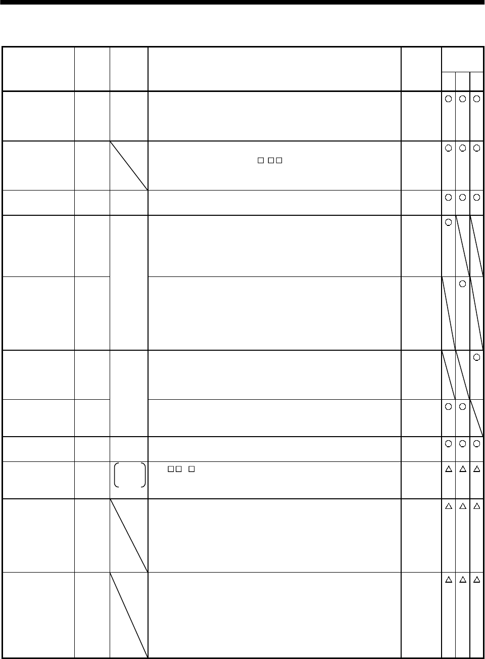
Limiting speed VLC VLC turns on when speed reaches the value limited using any of
the internal speed limits 1 to 7 (parameter No. 8 to 10, 72 to 75)
or the analog speed limit (VLA) in the torque control mode.
VLC turns off when servo on (SON) turns off.
DO-1
Limiting torque TLC
CN1B
6
TLC turns on when the torque generated reaches the value set to
the internal torque limit 1 (parameter No. 28) or analog torque
limit (TLA).
DO-1
Zero speed ZSP CN1B
19
ZSP turns on when the servo motor speed is zero speed (50r/min)
or less. Zero speed can be changed using parameter No. 24.
DO-1
Electromagnetic
brake interlock
MBR CN1B
19
Set " 1 " in parameter No. 1 to use this parameter. Note that
ZSP will be unusable.
MBR turns off when the servo is switched off or an alarm occurs.
DO-1
Warning WNG To use this signal, assign the connector pin for output using
parameter No.49. The old signal before assignment will be
unusable.
When warning has occurred, WNG turns on.
When there is no warning, WNG turns off within about 1s after
power-on.
DO-1
Battery warning BWNG To use this signal, assign the connector pin for output using
parameter No.49. The old signal before assignment will be
unusable.
BWNG turns on when battery cable breakage warning (AL. 92) or
battery warning (AL. 9F) has occurred.
When there is no battery warning, BWNG turns off within about
1s after power-on.
DO-1