SPLIT-TYPE AIR CONDITIONERS INDOOR UNIT No. OBH568 SERVICE MANUAL Models MFZ-KA09NA MFZ-KA12NA MFZ-KA18NA Outdoor unit service manual MXZ-B NA Series (OBH560) CONTENTS 1. TECHNICAL CHANGES······································· 2 2. PART NAMES AND FUNCTIONS ····················· 2 3. SPECIFICATION ················································ 4 4. OUTLINES AND DIMENSIONS ························ 5 5. WIRING DIAGRAM············································ 6 6.
1 TECHNICAL CHANGES MFZ-KA09NA MFZ-KA12NA MFZ-KA18NA 1.
ACCESSORIES MFZ-KA09NA MFZ-KA12NA MFZ-KA18NA Drain hose Remote controller holder Fixing screw for 3.5 x 1.
3 SPECIFICATION Indoor model Power supply V, phase, Hz Max. fuse size (time delay)/ Disconnect switch A COOL Dry CFM Airflow (Wet) Super High - High - Med. Low - Quiet HEAT Dry CFM Sound level Cooling dB(A) Super High - High - Med. Heating dB(A) Low - Quiet Cond. drain connection O.D. in. W Dimensions D in. H Weight Ib.
4 OUTLINES AND DIMENSIONS 5-5/32 4- 1/4 Hole 5-5/32 9/32 Unit: inch MFZ-KA09NA MFZ-KA12NA MFZ-KA18NA 13-1/8 23-11/32 14-5/16 Installation plate 1-27/32 Air in 23-5/8 3-3/4 7/16 drain 5-13/32 15/32 1-25/32 1-6/16 2-3/8 5-1/16 5-25/32 4-5/16 17-7/8 2-3/8 3-5/32 2-27/32 6-1/8 3/4 20 2-3/8 4-27/32 2-1/8 2-3/8 15/32 2-3/8 Gas pipe 09, 12: 3/8(flared) 18: 1/2(flared) Liquid pipe 1/4(flared) Air out 4-15/16 3/4 2-3/8 4-5/8 13-9/32 5 6-1/2 8-1/16 More than 3-7/8mm More than 3-7
5 WIRING DIAGRAM MFZ-KA09NA MFZ-KA12NA MFZ-KA18NA 6
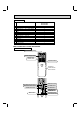
6 REFRIGERANT SYSTEM DIAGRAM MFZ-KA09NA MFZ-KA12NA MFZ-KA18NA Unit: inch Refrigerant pipe 3/8 (MFZ-KA09/12NA) Refrigerant pipe 1/2 (MFZ-KA18NA) (with heat insulator) Indoor heat exchanger Indoor coil thermistor RT12 (main) Distributor Flared connection Indoor coil thermistor RT12, RT14, RT15 (main) RT13 (sub) Room temperature thermistor RT11 Flared connection Refrigerant pipe 1/4 (with heat insulator) Refrigerant flow in cooling Refrigerant flow in heating 7
7 SERVICE FUNCTIONS MFZ-KA09NA MFZ-KA12NA MFZ-KA18NA 7-1. TIMER SHORT MODE For service, set time can be shortened by short circuit of JPG and JPS on the electronic control P.C. board. The time will be shortened as follows. (Refer to 9-7.) Set time: 1-minute 1-second Set time: 3-minutes 3-seconds (It takes 3 minutes for the compressor to start operation. However, the starting time is shortened by short circuit-of JPG and JPS.) 7-2. P.C.
7-3. AUTO RESTART FUNCTION When the indoor unit is controlled with the remote controller, the operation mode, the set temperature, and the fan speed are memorized by the indoor electronic control P.C. board. The “AUTO RESTART FUNCTION” sets to work the moment power is restored after power failure. Then, the unit will restart automatically. Operation If the main power has been cut, the operation settings remain. After the power is restored, the unit restarts automatically according to the memory.
8 MICROPROCESSOR CONTROL MFZ-KA09NA MFZ-KA12NA MFZ-KA18NA WIRELESS REMOTE CONTROLLER Signal transmitting section Operation display section OPERATE/STOP (ON/OFF) button Temperature buttons Indication of remote controller model is on back ra w.).
8-1. COOL ( ) OPERATION (1) Press OPERATE/STOP (ON/OFF) button. OPERATION INDICATOR lamp of the indoor unit turns ON with a beep tone. (2) Select COOL mode with OPERATION SELECT button. (3) Press TEMPERATURE buttons (TOO WARM or TOO COOL button) to select the desired temperature. The setting range is 61 ~ 88°F (16 ~ 31°C). 1. Coil frost prevention The compressor operational frequency is controlled by the temperature of the indoor heat exchanger to prevent the coil from frosting.
8-5. AUTO VANE OPERATION Horizontal vane (1) Vane motor drive These models are equipped with a stepping motor for the horizontal vane. The rotating direction, speed, and angle of the motor are controlled by pulse signals (approx. 12 V) transmitted from indoor microprocessor. (2) The horizontal vane angle and mode change as follows by pressing VANE CONTROL button. (3) Positioning The vane presses the vane stopper once to confirm the standard position and then moves to the set angle.
1.How to set to blow out air from the upper and lower air outlets: 2.How to set to blow out air from the upper air outlet only: Set the air outlet selection switch to Set the air outlet selection switch to . . Air blows out automatically from the upper and lower air outlets as shown in the table below. NOTE 2: Set the air outlet selection switch to the end correctly. Otherwise, air outlet cannot be selected as intended.
(11) ECONO COOL ( ) operation (ECONOmical operation) When ECONO COOL button is pressed in COOL mode, set temperature is automatically set 4°F (2°C) higher. Also the horizontal vane swings in various cycle according to the temperature of indoor heat exchanger (indoor coil thermistor). SWING operation makes you feel cooler than set temperature. So, even though the set temperature is higher, the air conditioner can keep comfort. As a result, energy can be saved.
8-7. SMART SET ( ) OPERATION 1. How to SET SMART SET operation (1) Press OPERATE/STOP (ON/OFF) button. (2) Select COOL, HEAT or ECONO COOL mode. (3) Press SMART SET button. (4) Set the temperature, fan speed, and airflow direction for SMART SET operation. NOTE: • SMART SET operation cannot be selected during DRY or AUTO mode operation. • The setting range of HEAT mode in SMART SET operation is 50°F (10°C) and 61 - 88°F (16 - 31°C). • 2 settings can be saved. (One for COOL/ECONO COOL, one for HEAT) 2.
9 TROUBLESHOOTING MFZ-KA09NA MFZ-KA12NA MFZ-KA18NA 9-1. CAUTIONS ON TROUBLESHOOTING 1. Before troubleshooting, check the following 1) Check the power supply voltage. 2) Check the indoor/outdoor connecting wire for miswiring. 2. Take care of the following during servicing 1) Before servicing the air conditioner, be sure to turn OFF the unit first with the remote controller, and then after confirming the horizontal vane is closed, turn OFF the breaker and/or disconnect the power plug.
9-2. FAILURE MODE RECALL FUNCTION Outline of the function This air conditioner can memorize the abnormal condition which has occurred once. Even though OPERATION INDICATOR lamp indication listed on the troubleshooting check table (9-4.) disappears, the memorized failure details can be recalled. This mode is very useful when the unit needs to be repaired for the abnormality which does not recur. 1.
2. Indoor unit failure mode table NOTE: Blinking patterns of this mode differs from the ones of Troubleshooting check table (9-4.). Left lamp of Right lamp of OPERATION OPERATION INDICATOR lamp INDICATOR lamp Not lighted Abnormal point (Failure mode) Not lighted Check point Normal Countermeasure – – 1-time flash every 0.5-second Not lighted Room temperature thermistor When the room temperature thermistor short or open circuit is detected every 8 seconds during operation. 2-time flash 2.
9-3. INSTRUCTION OF TROUBLESHOOTING Start Indoor unit operates. Outdoor unit does not operate. Outdoor unit operates only in Test Run operation. Check room temperature thermistor. Refer to 9-7. "Test point diagram and voltage". Indoor unit operates. Outdoor unit does not operate normally. Indoor unit does not receive the signal from remote controller. Outdoor unit does not operate even in Test Run operation. Unit does not operate normal operation in COOL or HEAT mode.
9-4. TROUBLESHOOTING CHECK TABLE OPERATION INDICATOR Lighted Blinking · Flashing of OPERATION INDICATOR lamp (left-hand side lamp) indicates abnormalities. Not lighted NOTE: Before taking measures, make sure that the symptom reappears for accurate troubleshooting. Self check table No. Abnormal point 1 Mis-Wiring or serial signal Operation indicator lamp Left lamp flashes. 0.5-second ON Symptom Check point Indoor unit and outdoor unit do not operate.
OPERATION INDICATOR Lighted Blinking Not lighted No. 1 Abnormal point MXZ type Operation mode setting · Flashing of OPERATION INDICATOR lamp (right-hand side lamp) indicates abnormality. · OPERATION INDICATOR lamp (left-hand side lamp) is lighted. Operation indicator lamp Right lamp flash 2.5-second OFF Symptom Check point Outdoor unit operates but indoor unit does not operate.
9-6. TROUBLESHOOTING FLOW When the left lamp of OPERATION INDICATOR lamp flashes 3 times and the right lamp of OPERATION INDICATOR lamp is not lighted. Indoor fan does not operate. A -1. Check of indoor fan motor (upper) The indoor fan motor error has occurred, and the indoor fan doesn't operate. Pay careful attention to the high voltage on the fan motor connector CN211. Turn OFF the power supply.
When the left lamp of OPERATION INDICATOR lamp flashes 3 times and the right lamp of OPERATION INDICATOR lamp flashes ON and OFF every 0.5-second. Indoor fan does not operate. A -2. Check of indoor fan motor (lower) The indoor fan motor error has occurred, and the indoor fan does not operate. Pay careful attention to the high voltage on the fan motor connector CN212. Turn OFF the power supply.
B Check of remote controller and indoor electronic control P.C. board Check if the remote controller is exclusive for this air conditioner. Switch on the remote controller. Is the LCD display on the remote controller visible? No Replace the batteries. (Refer to 9-1.4.) (not clear) Yes Remove the batteries, then set them back and press RESET button. (Refer to 9-1.4.) Check if the unit operates with the remote controller.
The unit cannot be operated with the remote controller. Also, OPERATION INDICATOR lamp does not light up by pressing EMERGENCY OPERATION switch. C Check of indoor P.C. board and indoor fan motor Turn OFF the power supply. Remove indoor fan motor connector CN211/ CN212 and vane motor connector CN151/ CN152 from the indoor electronic control P.C. board and turn ON the power supply. Turn OFF the power supply. Measure the resistance between CN211/ CN212 and of the indoor fan motor connector.
When the left lamp of OPERATION INDICATOR lamp flashes ON and OFF in every 0.5-second. Outdoor unit does not operate. D How to check miswiring and serial signal error Turn OFF the power supply. Is there rated voltage of 230 VAC in the power supply? No Check the power supply. Yes Turn ON the power supply. Is there 230 VAC between outdoor terminal block S1 and S2? No Check the wiring. Yes Press EMERGENCY OPERATION switch once.
When the left lamp of OPERATION INDICATOR lamp flashes 15-time. Indoor unit and outdoor unit do not operate. E Check of damper After performing the check, make sure to release the failure mode recall function. Turn OFF the power supply. Is there anything that interferes the opening or closing movement of the damper? Yes Remove the object. No Turn ON the power supply. While pressing both OPERATION SELECT button and TOO COOL button on the remote controller at the same time, press RESET button.
F Electromagnetic noise enters into TV sets or radios Is the unit earthed? No Earth the unit. Yes Is the distance between the antennas and the indoor unit within 3 m, or is the distance between the antennas and the outdoor unit within 3 m? Yes Extend the distance between the antennas and the indoor unit, or the antennas and the outdoor unit.
9-7. TEST POINT DIAGRAM AND VOLTAGE MFZ-KA09NA MFZ-KA12NA MFZ-KA18NA Indoor electronic control P.C. board Room temperature thermistor RT11 FUSE (F11) T3.15AL250V Power supply input 208/230 VAC 5 VDC Indoor coil thermistor RT14 (MAIN 2) Indoor coil thermistor RT13 (SUB) Indoor coil thermistor RT12 (MAIN 1) Indoor coil thermistor RT15 (MAIN 3) Release of Auto restart function Solder the Jumper wire to JR07. (Refer to 7-3.) short mode point } Timer JPG, JPS (Refer to 7-1.
10 DISASSEMBLY INSTRUCTIONS <"Terminal with locking mechanism" Detaching points> The terminal which has the locking mechanism can be detached as shown below. There are two types (refer to (1) and (2)) of the terminal with locking mechanism. The terminal without locking mechanism can be detached by pulling it out. Check the shape of the terminal before detaching. (1) Slide the sleeve and check if there is a locking lever or not.
OPERATING PROCEDURE PHOTOS 2. Removing the electronic control P.C. board and the display receiver P.C. board (1) Remove the panel. (Refer to 1.) (2) Remove the screw of the electrical cover, and then the electrical cover. (See Photo 3.) (3) Remove the screw of the indoor/outdoor connecting wire, and then the indoor/outdoor connecting wire. (4) Unhook the lamp cover from the catch. (See Photo 4.) (5) Open the lamp cover. Pull out the display receiver P.C.
OPERATING PROCEDURE PHOTOS Photo 6 4. Removing the horizontal vane motor unit (1) Remove the panel. (Refer to 1.) (2) Remove the screws of the horizontal vane motor unit and pull out the horizontal vane motor unit. (See Photo 6.) (3) Disconnect the connector from the horizontal vane motor unit. Screw of the horizontal vane motor unit 5. Removing the indoor fan motor (upper) (1) (2) (3) (4) Remove the panel. (Refer to 1.) Remove the electrical box. (Refer to 3.) Remove the nozzle (upper). (See Photo 7.
OPERATING PROCEDURE PHOTOS 6. Removing the damper lock motor, the damper motor and the damper limit switch (1) Remove the panel. (Refer to 1.) (2) Remove the screws of the nozzle assembly (lower). (See Photo 9.) (3) Remove the drain hose from the nozzle assembly (lower) and pull out the nozzle assembly (lower) toward you. (4) Remove the tape fixing the lead wires of the damper motor and the damper lock motor from the nozzle assembly . (See Photo 10.) (5) Remove the screws of the damper lock motor.
HEAD OFFICE: TOKYO BLDG., 2-7-3, MARUNOUCHI, CHIYODA-KU, TOKYO100-8310, JAPAN Copyright 2010 MITSUBISHI ELECTRIC ENGINEERING CO.,LTD Distributed in Jan. 2010. No. OBH568 7 Made in Japan New publication, effective Jan. 2010 Specifications subject to change without notice.