
Service manual
25
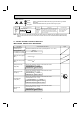
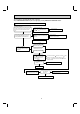
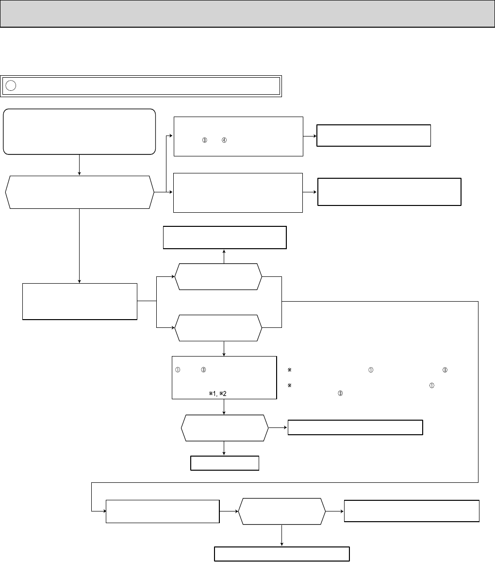
C Check of indoor P.C. board and indoor fan motor
The unit cannot be operated with the remote controller.
Also, OPERATION INDICATOR lamp does not light up by pressing EMERGENCY OPERATION switch.
Yes
No
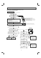
1. The fan motor connector's lead wire is red, whereas is black.
2. Connect "+" of the tester to fan motor connector's lead
wire, and "-" to lead wire, otherwise the resistance cannot be
measured properly.
Yes
No
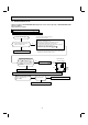
Does the unit operate with the remote controller?
Does OPERATION INDICATOR lamp light up by
pressing EMERGENCY
OPERATION switch?
Turn OFF the power supply.
Remove indoor fan motor connector CN211/ CN212 and
vane motor connector CN151/ CN152 from the indoor
electronic control P.C. board and turn ON the power
supply.
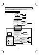
Turn OFF the power supply.
Measure the resistance of the horizontal vane
motor coil.
Refer to 9-5.
Turn OFF the power supply.
Measure the resistance between CN211/
CN212 and of the indoor fan motor
connector.
Short/ open circuit:
Replace the indoor fan motor.
Short/ open circuit:
Replace the horizontal vane motor and the indoor
electronic control P.C. board.
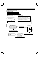
Turn OFF the power supply.
Check both “parts side” and “pattern
side” of the indoor electronic control P.C.
board visually.
Replace the varistor (NR11) and fuse (F11).
Are the varistor (NR11) burnt
and the fuse (F11) blown?
Be sure to check both the fuse
and the varistor in any case.
No
Yes
No
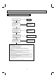
Is the fuse (F11) blown only?
Yes
No
Is the resistance 1MΩ
or more?
Measure the resistance between
(+) and (-) of the indoor fan
motor connector (to CN211/CN212
on the indoor electronic control
P.C. board).
Replace the fuse (F11).
Replace the fuse (F11) and the indoor fan motor.
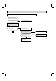
Is the resistance
approx. 4Ω?
Measure the cement resistance R111 on
the indoor electronic control P.C. board.
Replace the indoor electronic control P.C. board.
Replace the indoor electronic control P.C. board
and the indoor fan motor.
Yes