PHV HEAT PUMP RANGE AIR CURTAINS INSTALLATION, OPERATION & MAINTENANCE INSTRUCTIONS For use with Mr Slim units PLEASE READ THESE INSTRUCTIONS CAREFULLY BEFORE ATTEMPTING INSTALLATION Thermoscreens Ltd St. Mary’s Road Nuneaton Warwickshire England CV11 5AU Email: sales@thermoscreens.com Tel: +44 (0) 24 7638 4646 Fax: +44 (0) 24 7638 8578 www.thermoscreens.
Thermoscreens / Mitsubishi Electric Heat Pump Warm Air Curtain System Communications Link Manual On/Off Control and Permanent mains electrical supply (from local switched spur) for x Fans x Mitsubishi Electric Interface PCB x Defrost electric heaters (if used) Heat Setting Control Heat Pump Air Curtain Optional BMS Control Interface Board Mitsubishi Electric Outdoor Unit Manual Room Control Procon A32/M The Heat Pump Warm Air Curtain System consists of :• a Thermoscreens 'PHV Air Curtain' fitted wi
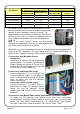
UNPACKING THE PHV HEAT PUMP AIR CURTAIN The following items are supplied and packaged within the air curtain box. PHV Heat Pump Air Curtain Wall Brackets and Fixing Bolts Please note end caps are supplied loose to be fitted during installation Manual Room Control If anything is missing or damaged please contact your place of purchase immediately. There will also be a 'Mr Slim Outdoor Unit' supplied by Mitsubishi Electric.
INSTALLATION OF THE HEAT PUMP AIR CURTAIN The air curtain has been designed to be surface mounted inside of the building and located horizontally over a doorway. It must not be installed outside of the building, or built into a cabinet or recessed in anyway. The air curtain is intended for use as a heating only unit. Location The air curtain must be mounted so the discharge grille is between 1.8m minimum and 3.75m maximum above floor level and situated as close to the doorway as possible.
250 min. for pipes 9901025-2 255 1400 700 1300 800 N/A 800 N/A B (mm) C (mm) D (mm) E (mm) 650 1746 1196 A (mm) 168 36 B A C E Hot Gas Refrigerant Connection Holes for M10 drop rods 4 for 1m unit, 6 for 1.
Mitsubishi Electric Outdoor Unit The Mitsubishi Electric Outdoor Unit is selected to match its refrigerant heat output to the size of the Air Curtain. See table below for size of outdoor unit to be used together with performance data for the air curtain. Heat Output (kW) Air Curtain Mr Slim Outdoor Unit @outdoor air 7/6°C db/wb Full Heat Half Heat Max. Air Volume Flow Rate Max. Noise Level (m3/h) dB(A) @3m PHV1000 DXE HO PUHZ-RP71VHA 8.6 5.34 1400 56 PHV1500 DXE LO PUHZ-RP71VHA 10.1 5.
manufactured in accordance with the Pressure Equipment Directive and the installation must be carried out to a good standard of workmanship. Remove the protective plastic film on top of the air curtain before starting work. Use a heat sink on the copper pipes when brazing to reduce the transfer of heat to the inside of the air curtain where sensitive components are located.
Air Curtain PHV1000 DXE HO PHV1500 DXE LO PHV1500 DXE HO PHV2000 DXE LO PHV2000 DXE HO 230V/1ph/50Hz if defrost electric heaters are not used Rated Electrical Rated Current (A) Power Input (kW) 0.3 0.35 0.35 0.5 0.5 400V/3ph/50Hz if defrost electric heaters are required Rated Electrical Rated Current per Power Input (kW) phase (A) 1.3 1.8 1.8 2.7 2.7 4.8 7.8 7.8 9.5 9.5 7.8 12.7 12.7 15.7 15.
If a BMS or Centralised Controller is to be used instead of Manual Control it is not necessary to wire to terminals 1-4. NB. Do not install Manual Room Control and BMS/Centralised Control together as they can interfere with each other. Recommended wire size for electrical connections are as follows: 1 1.0mm2 2 2.5mm2 max for access 3 0.75mm2 Do not use cable size of more than 2.5mm2 or connecting the cable is difficult.
9901025-2 K1 K1 1m unit 3 x 1.5kW = 4.5kW 1.5m unit 3 x 2.5kW = 7.5kW 2m unit 3 x 3.0kW = 9kW OPTIONAL LOW SPEED CONTROLLER PROCON A32/M 2-core double insulated flex (carries signal voltages) 1 2 A-CONTROL SUB INTERFACE E S1 S2 S3 3 4 Electrical Supply for Outdoor Unit 400V/3ph/50Hz or 230V/1ph/50Hz L1 L2 L3 N SITE WIRING WIRING DIAGRAM – PHV HEAT PUMP AIR CURTAIN 1.3A for PHV1000DX 1.8A for PHV1500DX 2.
COMMISSIONING THE HEAT PUMP AIR CURTAIN Ensure that the electrical supply to both the Mitsubishi Electric Outdoor Unit and the local electrical supply to the Air Curtain are switched off. Air Curtain Checks Check that the components inside the air curtain are as shown in the picture below. Check that the thermal overheat cut-out switch has not ‘tripped’. Push down on the red button on the top of the thermal overheat switch - if it has tripped it will click back on.
BMS Control or Centralised Controller On the Mitsubishi Electric Interface PCB check that the BMS Fan-Run Connection is plugged into position CNX1 (as shown on previous page and Wiring Diagram).
connection if removed earlier. Ensure cables are not trapped inside and refit retaining screw. The Filter Indicator Schedule can now be changed from its default setting if required (see page 15). Replace the bottom access panel, air inlet grilles (with filters) and plastic end caps (see “To gain access inside the Air Curtain” page 7).
Note 1: The set point and fan speed of the air curtain cannot be altered through the Manual Room Control. The set point is hard coded to 28ºC * via dip switch SW2 on the Mitsubishi Interface PCB in the air curtain. The fan speed is set manually at commissioning using the 3 speed fan switch inside the air curtain, as described above.
The factory set default schedule is suitable for most applications. However, the actual frequency of cleaning required will depend on the environment. Two alternative filter indicator schedules are available, and can be selected by changing the ‘jumper’ position (marked 1, 2 or 3) on the Filter Indicator pcb.
switch SW2 on the Mitsubishi Interface PCB in the air curtain (see Page 12). It is vital they understand that the air curtain must not be run in COOL or AUTO mode. Ensure that all instructions and manuals are handed to the end user or their representative.
SERVICING THE HEAT PUMP AIR CURTAIN Vacuum Clean the Air Inlet Grilles / Filters (Weekly, or when the Filter Dirty Indicator shows PERMANENT RED) With the air curtain switched OFF, a vacuum cleaner with an extension tube and brush attachment at its end should be used to clean the face of the air inlet grilles. This is important to minimise the build-up of dust and lint on the air filters at the back of the inlet grilles which will affect the performance of the air curtain.
Remove the bottom access panel by unfastening the panel fixing screws (2 on PHV1000, 4 on PHV1500 & 2000 units) and sliding the access panel out forwards. Clean the inside of the access panel. location of screw access panel Vacuum clean and remove any build-up of dust, dirt and debris within the air-curtain, especially on the face of the coil and the electric heating elements. Note: Fan motors are permanently lubricated and require no additional lubrication.
Fault Conditions If the Thermoscreens Heat Pump Warm Air Curtain System does not operate as expected refer to the fault finding table below: Symptom Possible Cause Electrical power is not switched on at both the Mitsubishi Electric Outdoor Unit and at the local electrical isolator next to the Thermoscreens Air Curtain Air curtain does not operate BMS Control: Air curtain is set to 'Off'.
Warranty If any problems are encountered with the heat pump warm air curtain please contact your Mitsubishi Electric Service Agent. Care has been taken in compiling these instructions to ensure they are correct, although Thermoscreens Ltd. disclaims all liability for damage resulting from any inaccuracies and/or deficiencies in this documentation. Thermoscreens Ltd. retain the right to change the specifications stated in these instructions. Thermoscreens Ltd St.
Thermoscreens Ltd St.