
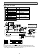
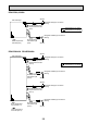
Technical data

52
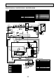
PSA-RP71GA PSA-RP100GA PSA-RP125GA PSA-RP140GA
1357
MF
ORN
C
RED
BLK
BLU
YLW
13 13 13 12
1
2
2
1
3
13
ML
YLW
YLW
BLK
ORN
YLW
YLW
ORN
S1
S2
S3
WHT
WHT
WHT
BRN
ORN
RED
I.B
FAN
(WHT)
LOUVER
CNL
(YLW)
X4X5X6
X6
X5 X4
X2
FUSE
X2
LED3 LED2 LED1
SWE
ON
OFF
POWER
CNDK
(RED)
POWER
CND
(ORN)
POWER
CN2D
(WHT)
WIRELESS
CN90
(WHT)
2
1
REMOCON
CN22
(BLU)
CN32
CN2L
2
1
TB6
2
2
1
1
2
1
LIQUID
CN21
(WHT)
INTAKE
CN20
(RED)
PIPE
CN29
(BLK)
CN24 CN41
CN51
R.B
TRANSMISSION
WIRES DC12V
BLU
BLU
TH1
TH2
TH5
SW1SW2
TB4
REDRED
WHT
RED
BLU
GRN/YLW
88H
FS1FS2
H
53
1
2
L
N
TB2
POWER SUPPLY
~(1 PHASE)
230V 50Hz
2
1
6
5
RED
RED
YLW
26H
88H
YLW
YLW
16
HEATER
CN24
(YLW)
I.B
PSH -P.GAH
models only
INDOOR UNIT
The black square () indicates a switch position.
Please set the voltage using the
remote controller.
For the setting method, please refer to
the indoor unit Installation Manual.
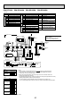
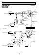
INDOOR/OUTDOOR
COMMUNICATION
CN3C
(BLU)
Refer to tables 1
and 2 for service PCB.
P. B
CNSK
(RED)
CN2S
(WHT)
DC13.1V
TO
OUTDOOR
UNIT
3131
POWER
CND
(ORN)
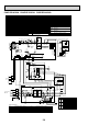
INDOOR/OUTDOOR
COMMUNICATION
CN3C
(BLU)
TB2
TB4
POWER SUPPLY
~(1PHASE)
230V 50Hz
RED
BLU
GRY/YLW
RED
BLU
TO
OUTDOOR
UNIT
L
S1
S2
S3
N
I.B
YLW
ORN
ORN
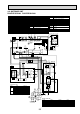
BRN
1 (Fig.1)
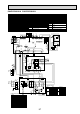
Service board
SW2
Table 2
1 2 3 4 5
MODELS
PSA-RP71GA
PSH-P71GAH
PSA-RP100GA
PSH-P100GAH
PSA-RP125GA
PSH-P125GAH
PSA-RP140GA
PSH-P140GAH
ON
OFF
1 2 3 4 5
ON
OFF
1 2 3 4 5
ON
OFF
1 2 3 4 5
ON
OFF
Service board
SW2
Table 1
1 2 3 4 5
MODELS
PSA-RP.GA
PSH-P.GAH
ON
OFF
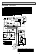
P. B
INDOOR POWER BOARD
SYMBOL NAME
[LEGEND]
SYMBOL NAME SYMBOL NAME
I.B
I.B
INDOOR CONTROLLER BOARD
FUSE FUSE (T6.3AL250V)
CN2L CONNECTOR (LOSSNAY)
CN32
CONNECTOR (REMOTE SWITCH)
CN41 CONNECTOR (HA TERMINAL-A)
CN51
CONNECTOR (CENTRALLY CONTROL)
SW1
SWITCH (MODEL SELECTION) See Table 1.
SW2
SWITCH (CAPACITY CODE) See Table 2.
SWE
SWITCH (EMERGENCY OPERATION)
X4 RELAY (FAN MOTOR)
X5 RELAY (FAN MOTOR)
X6 RELAY (FAN MOTOR)
X2
RELAY (LOUVER)
POWER SUPPLY (R.B)
LED1 POWER SUPPLY (I.B)
LED2
TRANSMISSION (INDOOR-OUTDOOR)
LED3
WIRED REMOTE CONTROLLER BOARD
TERMINAL BLOCK (REMOTE CONTROLLER
TRANSMISSION LINE)
R.B
TB6
HEATER
HEATER
THERMAL FUSE (110°C16A)
H
FS1,2
HEATER THERMAL SWITCH
26H
HEATER CONTACTOR
88H
C CAPACITOR (FAN MOTOR)
FAN MOTOR
MF
LOUVER MOTOR
ML
TB2
TERMINAL BLOCK
(INDOOR/OUTDOOR CONNECTING LINE)
TB4
TERMINAL BLOCK (HEATER) PSH-P·GAH
models only or option for PSA-RP·GA models.
ROOM TEMP.THERMISTOR
(0°C/15k, 25°C/5.4k DETECT)
PIPE TEMP.THERMISTOR/LIQUID
(0°C/15k, 25°C/5.4k DETECT)
COND./EVA.TEMP.THERMISTOR
(0°C/15k, 25°C/5.4k DETECT)
TH1
TH2
TH5
Notes:
1. SymboIs used in wiring diagram above are, : Connector, : Terminal (block).
2. Indoor and outdoor connecting wires have poIarities, make sure to match terminal
numbers (S1, S2, S3) for correct wirings.
3. Since the outdoor side electric wiring may change, be sure to check the outdoor unit
electric wiring diagram for servicing.
4. This diagram shows the wiring of indoor and outdoor connecting wires (specification of 230V),
adopting superimposed system for power and signal.
+1: When supplying power separately to indoor and outdoor units, refer to Fig 1.
+2: For power supply system of this unit, refer to the caution label located near this diagram.