
Installation manual


19
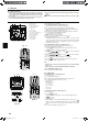
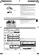
(1) Press the
TEST
button for 3 seconds to
activate the maintenance mode.
(2) Press the TEMP. buttons to set the refrigerant address.
MAINTENANCE
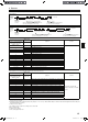
(3) Select the data you want to display.
MENU
ON/OFF
Compressor
information
COMP ON
x10 HOURS
COMP ON
x100 TIMES
COMP ON
CURRENT (A)
Cumulative
operation time
ON/OFF
number
Operation
current
Display
Display
Display
OUTDOOR UNIT
H•EXC. TEMP
OUTDOOR UNIT
OUTLET TEMP
OUTDOOR UNIT
OUTDOOR TEMP
Heat exchanger
temperature
Comp discharge
temperature
Outdoor ambient
temperature
Display
Outdoor unit
information
INDOOR UNIT
INLET TEMP
INDOOR UNIT
H•EXC. TEMP
INDOOR UNIT
FILTER USE H
Indoor room
temperature
Heat exchanger
temperature
Filter operation
time
Display
Indoor unit
information
* The filter operation time displayed is the number of hours the filter has been
used since the filter reset was performed.
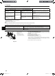
(4) Press the
FILTER
button.
(5) The data is displayed in .
(Airflow temperature display example)
Blinking
Waiting for
response
Approx.
10 sec.
64
* Repeat steps (2) to (5) to check another data.
(6) Press the
TEST
button for 3 seconds or press the
ON/OFF
button to
deactivate the maintenance mode.
Stable operation
Using the maintenance mode, the operation frequency can be fixed and the op-
eration can be stabilized. If the air conditioner is stopped, use the following pro-
cedure to start this operation.
COOL
STABLE MODE
HEAT
STABLE MODE
STABLE MODE
CANCEL
Stable cooling
operation
Stable heating
operation
Stable operation
cancellation
Display
Press the
MODE
button to select the operation mode.
Press the
FILTER
button.
Waiting for
stable operation
Display
Stable
operation
10-20 min.
* You can check the data using steps (3) to (5) of the maintenance mode opera-
tion procedures while waiting for the stable operation.
Display example (Comp discharge temperature 64˚C)
Display
PAR-21MAA
B
B
C
C
C
D
D
A
A
A
A
A
A
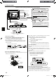
9. Installing the grille
Maintenance mode operation procedures
10. Easy maintenance function (For PUHZ-(H)RP application only)
By using the maintenance mode, you can display many types of maintenance data
on the remote controller such as the heat exchanger temperature and compressor
current consumption for the indoor and outdoor units.
This function can be used whether the air conditioner is operating or not.
During air conditioner operation, data can be checked during either normal opera-
tion or maintenance mode stable operation.
* This function cannot be used during the test run.
* The availability of this function depends on the connecting outdoor unit. Refer to
the brochures.
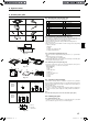
Fig. 9-11
Button
Vane motor
Up/down vanes
Connector
9.7. Locking the up/down airow direction (Fig. 9-11)
The vanes of the unit can be set and locked in up or down orientations depending
upon the environment of use.
• Set according to the preference of the customer.
The operation of the fixed up/down vanes and all automatic controls cannot
be performed using the remote controller. In addition, the actual position of the
vanes may differ from the position indicated on the remote controller.
1
Turn off the main power switch.
Injuries or an electrical shock may occur while the fan of the unit is rotating.
2
Disconnect the connector for the vane motor of the vent that you want to lock.
(While pressing the button, remove the connector in the direction indicated by the
arrow as shown in the diagram.) After removing the connector, insulate it with tape.
It also can be set by remote controller. Refer to 6.3.3.
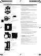
9.8. Check
•
Make sure that there is no gap between the unit and the grille, or between the grille
and the surface of the ceiling. If there is any gap between the unit and the grille, or
between the grille and the surface of the ceiling, it may cause dew to collect.
• Make sure that the wires have been securely connected.
• For PLP-6BAE, PLP-6BAMDE, PLP-6BALME, check the rotating movement of
the i-see sensor. If the i-see sensor does not rotate, review the procedure in “9.6.
Installation of i-see sensor corner panel”.
01_BH79D045K05_EN.indd 19 2012/09/18 (火) 午後 3:45:03