
User Manual


Technical Information
B/6
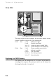
Jumper configurations
There are very few jumpers that will ever need changing, most of
them have been factory set for your system and its needs, but for
completeness, the details are given here.
Internal speaker operation
PL2 Next to outer SIMM socket, default position link pins 4
and 5 gives audio output to the internal speaker in mono.
Only to be removed in a system having internal stereo
speakers.
Internal ‘audio’ modem
PL4 Just along from the CD audio connection, default position
if no internal modem is fitted, link pins 3 and 4. Remove
only when fitting an internal modem supporting sound.
BIOS reprogramme
These links are for special purposes. Only to be used for an official
upgrade to the system BIOS. Do not move for any other reason.
PL5 Next to PL2, normal link 2 and 3. This link is used in the
event of a disaster occurring during an upgrade to the
system BIOS. Link moved to pins 1 and 2 will enable the
system to be booted up from an internal backup of the
BIOS held in a secure area in the system ROM.
PL6 Normal link 2 and 3, move to pins 1 and 2 to enable
BIOS reprogramming (requires specialist software).
Floppy disk control mode
PL13 Next to floppy disk ribbon connector, default position
link pins 3 and 4. To enable 3-mode operation of the
drive (not usual in Europe), link 1 to 3, and 2 to 4.