OB371_--1qxp 05.1.17 12:50 Page 1 SPLIT-TYPE, HEAT PUMP AIR CONDITIONERS No. OB371 SERVICE MANUAL Wireless type Models MSZ-FA25VA MSZ-FA35VA - E1 (WH) E1 (WH) CONTENTS Indication of model name MSZ-FA25VA - E1 MSZ-FA35VA - E1 1. TECHNICAL CHANGES ····································2 2. PART NAMES AND FUNCTIONS······················3 3. SPECIFICATION·················································5 4. NOISE CRITERIA CURVES ·······························6 5.
OB371_--1qxp 05.1.17 12:50 Page 2 1 TECHNICAL CHANGES MSZ-A09YV - E1 MSZ-A12YV - E1 ➔ MSZ-FA25VA - E1 ➔ MSZ-FA35VA - E1 1. Indication of capacity has been changed.(BTU base ➔kW base) 2. Controller method between indoor and outdoor has been changed. 3. Power supply method has been changed (change to supply from outdoor unit). 4. Power supply cord has been removed. 5. Indoor electronic control P.C. board has been changed. 6. Position of terminal block has been changed. 7.
OB371_--1qxp 05.1.17 12:50 Page 3 2 PART NAMES AND FUNCTIONS INDOOR UNIT MSZ-FA25VA - E1 MSZ-FA35VA - E1 Air inlet PLASMA AIR PURIFYING filter Front panel Panel PLASMA DEODORIZING filter Heat exchanger Fan guard Anti-mold air filter Air outlet Vertical vane Horizontal vane Remote controller Line flow fan Auto front panel When the unit starts operating, the front panel opens automatically to draw in air. When the unit stops operating, the front panel closes automatically.
OB371_--1qxp 05.1.17 12:50 Page 4 MSZ-FA25VA - E1 MSZ-FA35VA - E1 MSZ-FA25VA MSZ-FA35VA - ACCESSORIES 1 Installation plate 1 2 Installation plate fixing screw 4 o 25 mm 5 3 Remote controller holder 1 4 Fixing screw for 3 3.5 o 1.
OB371_--1qxp 05.1.17 12:50 Page 5 3 SPECIFICATION Indoor model MSZ-FA25VA - Function Cooling MSZ-FA35VA - E1 Cooling Heating Single phase 230V,50Hz Power supply Air flow(Super High) K /h Air flow(HighW/Med.W/LowW) K /h Power outlet A Running current ✽1 A Power input ✽1 W Auxiliary heater A(kW) Power factor ✽1 % Fan motor current ✽1 A Fan motor Model Dimensions WOHOD mm Weight kg Air direction Sound level(Super High) dB(A) Sound level(HighW/Med.
OB371_--1qxp 05.1.
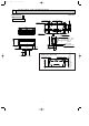
OB371_--1qxp 05.1.17 12:50 Page 7 5 OUTLINES AND DIMENSIONS Unit : mm 11o26 Oblong hole 155 155 335 55 Indoor unit 320 Wall hole [65 5 100 298 7 or more 198 { Drain hose [16 (Connected part O.D) 90 Insulation [28 106 19 Air out 159 58 102 Installation plate Liquid line [6.35 - 0.5m Gas line [9.52 - 0.43m Insulation [35 O.D [19 I.
OB371_--1qxp 05.1.17 12:50 Page 8 6 WIRING DIAGRAM MSZ-FA25VA - E1 MSZ-FA35VA - E1 INDOOR UNIT MODELS WIRING DIAGRAM 230V~ TB S1 S2 TO OUTDOOR UNIT CONNECTING 12-24V S3 BLK TAB3 INDOOR ELECTRONIC CONTROL P.C. BOARD F11 DB111 BLU RED 2 1 4 CN 111 NR11 1 2 3 4 5 6 LD104 GRN 5 CN 1R1 5 LD 101(A) 2 INTERLOCK SWITCH(FAN) MV1 MV2 SYMBOL DB111 F11 MF MP MT MV1 CN 110 LD 105(T) 3 8 CN 1T1 4 5 SW P.C. BOARD POWER MONITOR RECEIVER P.C.
OB371_--1qxp 05.1.17 12:50 Page 9 8 SERVICE FUNCTIONS MSZ-FA25VA - E1 MSZ-FA35VA - E1 8-1. TIMER SHORT MODE For service, set time can be shortened by short circuit of JPG and JPS the electronic control P.C. board. The time will be shortened as follows. (Refer to 9-7.) Set time : 1-minute ➔ 1-second Set time : 3-minute ➔ 3-second (It takes 3 minutes for the compressor to start operation. However, the starting time is shortened by short circuit of JPG and JPS.) 8-2. P.C.
OB371_--1qxp 05.1.17 12:50 Page 10 CN151 CN1T2 CN1T1 CN112 IC156 CN212 CN130 CN1R1 CN211 How to release “AUTO RESTART FUNCTION” 1Turn off the main power for the unit. 2Solder the Jumper wire to JR07 on the indoor electronic control P.C. board. (Refer to 9-7.) JR07 NOTE: • The operation settings are memorized when 10 seconds have passed after the indoor unit was operated with the remote controller.
OB371_--1qxp 05.1.17 12:50 Page 11 9 TROUBLESHOOTING MSZ-FA25VA - E1 MSZ-FA35VA - E1 9-1. Cautions on troubleshooting 1. Before troubleshooting, check the following: 1) Check the power supply voltage. 2) Check the indoor/outdoor connecting wire for mis-wiring. 2. Take care the following during servicing.
OB371_--1qxp 05.1.17 12:50 Page 12 6. How to remove and install PLASMA DEODORIZING / AIR PURIFYING filter units If PLASMA/WASH lamp on the indoor unit blinks, clean the filters as soon as possible. The lamp will start blinking when accumulated operating time exceeds 330 hours. (1) Switch the indoor unit OFF with the remote controller and disconnect the power supply plug and/ or turn OFF the breaker.
OB371_--1qxp 05.1.17 12:50 Page 13 INFORMATION FOR MULTI SYSTEM AIR CONDITIONER OUTDOOR UNIT : MXZ series Multi system air conditioner can connect two or more indoor units with one outdoor unit. •Unit won’t operate in case the total capacity of indoor units exceeds the capacity of outdoor units. Do not connect indoor units beyond the outdoor unit capacity. Operation indicator lamp flashes as shown in the figure below.
OB371_--1qxp 05.1.17 12:50 Page 14 9-2. Failure mode recall function Outline of the function This air conditioner can memorize the abnormal condition which has occurred once. Even though LED indication listed on the troubleshooting check table disappears, the memorized failure details can be recalled. This mode is very useful when the unit needs to be repaired for the abnormality which doesn't recur. 1.
OB371_--1qxp 05.1.17 12:50 Page 15 2. Flow chart of PLASMA DEODORIZING/PLASMA AIR PURIFYING power failure mode recall function Operational procedure There is a possibility that the plasma unit is abnormal. Confirm the presence of abnormality according to the following procedures. Confirm that the remote controller is in the failure mode recall function. W1. Regardless of normal or abnormal, a short beep is emitted as the signal is received.
OB371_--1qxp 05.1.17 12:50 Page 16 4. Indoor unit failure mode table NOTE: Blinking patterns of this mode differs from the ones of Troubleshooting check table(9-4.). POWER lamp Abnormal point (Failure mode) Detection method Check point Not lighted Normal – – 1-time flash every 0.5-second Room temperature thermistor When the room temperature thermistor short Refer to the characteristics of the room or open circuit is detected every 8 temperature thermistor (9-7.). seconds during operation.
OB371_--1qxp 05.1.17 12:50 Page 17 9-3. Instruction of troubleshooting w"Test Run operation" means the operation within 30 minutes after EMERGNCY OPERATION switch is pressed. Start Indoor unit operates. Outdoor unit doesn't operate. Indoor unit operates. Outdoor unit doesn't operate normally. Indoor unit doesn't receive the signal from remote controller. Outdoor unit operates in only Test Run operation. w Outdoor unit doesn't operate even in Test Run operation.
OB371_--1qxp 05.1.17 12:50 Page 18 9-4. Troubleshooting check table Lighted · Flashing of POWER lamp indicates abnormalities. Blinking Not lighted NOTE : Before taking measures, make sure that the symptom reappears for accurate troubleshooting. Self check table No. Abnormal point 1 Mis-Wiring or serial signal Operation indicator lamp POWER lamp flashes. 0.5-second ON Symptom Detection method Check point Outdoor unit does not operate.
OB371_--1qxp 05.1.17 12:50 Page 19 Lighted · Flashing of AREA lamp(left-hand side lamp) indicates abnormality. Blinking Not lighted NOTE : Before taking measures, make sure that the symptom reappears for accurate troubleshooting. Self check table No. Abnormal point 1 Indoor control system Operation indicator lamp Left lamp of AREA lamp flashes. 4-time flash Symptom Indoor unit and outdoor unit do not operate.
OB371_--1qxp 05.1.17 12:50 Page 20 9-5. Trouble criterion of main parts MSZ-FA25VA - E1 Part name Room temperature thermistor(RT11) Indoor coil thermistor (RT12(MAIN), RT13(SUB)) Indoor fan motor(MF) Horizontal vane motor(MV1) Vertical vane motor(MV2) i-see Sensor motor(MT) Front panel driving motor (MP) MSZ-FA35VA - E1 Check method and criterion Figure Measure the resistance with a tester. (Part temperature 10˚C ~ 30˚C) Normal 8 k" ~ 20 k" Abnormal Open or short-circuit Check 9-6. A.
OB371_--1qxp 05.1.17 12:50 Page 21 9-6. Troubleshooting flow When POWER lamp flashes 3-time. Indoor fan does not operate. A Check of indoor fan motor The indoor fan motor error has occurred, and the indoor fan doesn't operate. Turn OFF the power supply. Insert a stick such as a screw driver into the air outlet, and check if there is any catch in the rotation of the line flow fan.
OB371_--1qxp 05.1.17 12:50 Page 22 Indoor unit operates by pressing EMERGENCY OPERATION switch, but does not operate with the remote controller. B Check of remote controller and receiver P.C. board wCheck if the remote controller is exclusive for this air conditioner. Switch on the remote controller. Is LCD display on the the remote controller visible? No Replace the batteries. (Refer to 9-1.4.) (not clear) Yes Remove the batteries, then set them back and press RESET button. (Refer to 9-1.4.
OB371_--1qxp 05.1.17 12:50 Page 23 The unit does not operate with the remote controller. Also, POWER lamp does not light up by pressing EMERGENCY OPERATION switch. C Check of indoor electronic control P.C. board and indoor fan motor Turn OFF the power supply. Remove indoor fan motor connector CN211, vane motor connector CN151 front panel driving motor connector connector CN1U1 and i-see Sensor motor connector CN110 from the indoor electronic control P.C. board and turn ON the power supply.
OB371_--1qxp 05.1.17 12:50 Page 24 When POWER lamp flashes ON and OFF in every 0.5-second. Outdoor unit does not operate. D How to check mis-wiring and serial signal error Turn OFF the power supply. Is there rated voltage of 230V AC in the power supply? No Check the power supply. Yes Turn ON the power supply. Is there 230V AC between outdoor terminal block S1 and S2? No Check the wiring. Yes Press EMERGENCY OPERATION switch.
OB371_--1qxp 05.1.17 12:50 Page 25 When All lamps flash ON and OFF every 0.5-second. Indoor unit and outdoor unit do not operate. E Check of installation of the horizontal vane Start Turn OFF the power supply. Is the stopper of the horizontal vane locked to the indoor unit correctly? No Relock the stopper of the horizontal vane to the indoor unit. Refer to 9-1.5. Yes Turn ON the power supply.
OB371_--1qxp 05.1.17 12:50 Page 26 When PLASMA/WASH lamp flashes 2-time. wThe power failure mode for PLASMA DEODORIZING power is memorized when the failure mode is called. F Check of PLASMA DEODORIZING power After performing the check, make sure to release the failure mode recall function. High voltage (approx. -3.9kV) is generated during PLASMA DEODORIZING power operation. Pay careful attention and never touch PLASMA/WASH unit and the high-voltage lead part (red wire). Turn ON the power supply.
OB371_--1qxp 05.1.17 12:50 Page 27 When PLASMA/WASH lamp flashes 2-time. wThe power failure mode for PLASMA AIR PURIFYING power is memorized when the failure mode is called. G Check of PLASMA AIR PURIFYING power After performing the check, make sure to release the failure mode recall function. High voltage (approx. -3.9kV) is generated during PLASMA AIR PURIFYING power operation. Pay careful attention and never touch PLASMA/WASH unit and the high-voltage lead part (red wire). Turn ON the power supply.
OB371_--1qxp 05.1.17 12:50 Page 28 Indoor unit and outdoor unit do not operate. H Check of auto front panel Turn the remote controller ON. No Does the front panel automatically open? (Does it start to move?) Yes Is the connector of the front panel driving motor unit or the indoor electric control P.C. board unplugged? No Yes Plug in the connector and check from the start again.
OB371_--1qxp 05.1.17 12:50 Page 29 I Electromagnetic noise enters into TV sets or radios No Is the unit earthed? Earth the unit. Yes Is the distance between the antennas and the indoor unit within 3m, or is the distance between the antennas and the outdoor unit within 3m? Yes Extend the distance between the antennas and the indoor unit, or the antennas and the outdoor unit.
OB371_--1qxp 05.1.17 12:50 Page 30 9-7. Test point diagram and voltage MSZ-FA25VA - E1 MSZ-FA35VA - E1 Indoor electronic control P.C. board 5V DC 12V DC Cement resistance (R111) Indoor fan motor (CN211) 1311V DC 3(-) Fiducial terminal of cathode side on measuring high-voltage DC 415V DC 5(+)3-6V DC 6(+)0V DC or 15V DC Power supply input 230V AC Interlock switch(Fan) (CN1R1) { Room temperature thermistor (CN111) Varistor (NR11) SW P.C.
OB371_--2qxp 05.1.17 12:49 Page 31 10 DISASSEMBLY INSTRUCTIONS <"Terminal with locking mechanism" Detaching points> The terminal which has the locking mechanism can be detached as shown below. There are two types ( Refer to (1) and (2)) of the terminal with locking mechanism. The terminal without locking mechanism can be detached by pulling it out. Check the shape of the terminal before detaching. (1) Slide the sleeve and check if there is a locking lever or not.
OB371_--2qxp 05.1.17 12:49 Page 32 OPERATING PROCEDURE PHOTOS 2. Removing the electronic control P.C. board, the power monitor receiver P.C. board, i-see Sensor, SW P.C. board and the terminal block (1) Remove the horizontal vane, the panel (Refer to 1.) and the corner box. (2) Remove the screw of the V.A. clamp, and then the indoor/outdoor connecting wire.(See Photo 3.) (3) Remove the switch holder from the electrical cover. (See Photo 4.
OB371_--2qxp 05.1.17 12:49 Page 33 OPERATING PROCEDURE PHOTOS Photo 6 4. Removing the horizontal vane motor unit (1) Remove the horizontal vane and the panel. (Refer to 1.) (2) Remove the screws of the horizontal vane motor unit, and pull out the horizontal vane motor unit. (See Photo 6.) (3) Disconnect the connector from the horizontal vane motor unit. Screw of the horizontal vane motor unit Photo 7 5. Removing the vertical vane motor unit (1) Remove the horizontal vane, the panel (Refer to 1.
OB371_--2qxp 05.1.17 12:49 Page 34 OPERATING PROCEDURE PHOTOS 7. Removing the plasma power P.C. board Photo 11 (1) Remove the horizontal vane, the panel (Refer to 1.) and the corner box. (2) Remove the switch holder and the electrical cover. (Refer to 3.) (3) Disconnect the connector of the front panel driving motor from the electronic control P.C. board. (4) Remove the front panel driving motor.
OB371_--2qxp 05.1.17 12:49 Page 35 11 PARTS LIST MSZ-FA25VA - E1 (WH) MSZ-FA35VA - E1 (WH) 11-1. INDOOR UNIT STRUCTURAL PARTS 1 11-2. ACCESSORY AND REMOTE CONTROLLER 10 9 8 7 2 3 4 5 6 11-1. INDOOR UNIT STRUCTURAL PARTS No. 1 2 3 4 5 6 7 8 Part No.
OB371_--2qxp 05.1.17 12:49 Page 36 MSZ-FA25VA - E1 (WH) MSZ-FA35VA - E1 (WH) 11-3. INDOOR UNIT ELECTRICAL PARTS AND FUNCTIONAL PARTS 30 1 SAFETY DEVICE (PLASMA UNIT) 29 PLASMA POWER P.C.BOARD 25 26 24 20 28 31 2 27 SLEEVE BEARING 22 3 4 32 5 INTERLOCK SWITCH 6 (FAN) 7 21 23 8 18 SW P.C. BOARD 17 16 POWER MONITOR RECEIVER P.C. BOARD 15 18 14 13 POWER MONITOR RECEIVER P.C. BOARD HOLDER i-see Sensor MOTOR 11 12 i-see Sensor 11-4.
OB371_--2qxp 05.1.17 12:49 Page 37 11-3. INDOOR UNIT ELECTRICAL PARTS AND FUNCTIONAL PARTS No. Part No.
OB371_--2qxp 05.1.17 12:49 Page 38 12 OPTIONAL PARTS DEODORIZING CERAMIC FILTER Replacement of the deodorizing ceramic filter(about once every 6 years) Deodorizing ceramic filter is installed inside PLASMA DEODORIZING filter unit. The filter is fragile. Handle it with care. NOTE: PLASMA DEODORIZING filter unit may not operate properly if the deodorizing ceramic filter is not installed. Be sure to install the deodorizing ceramic filter. (1) Release the two knobs to open the filter unit.
OB371_--2qxp 05.1.
OB371_--2qxp 05.1.17 12:49 Page 40 HEAD OFFICE: MITSUBISHI DENKI BLDG., 2-2-3, MARUNOUCHI, CHIYODA-KU, TOKYO100-8310, JAPAN C Copyright 2005 MITSUBISHI ELECTRIC ENGINEERING CO.,LTD Distributed in Jan. 2005. No. OB371 6 Made in Japan New publication, effective Jan. 2005 Specifications subject to change without notice.