OB280-1.qxp 02.12.19 11:15 AM Page 1 SPLIT-TYPE, HEAT PUMP AIR CONDITIONER Revision: • MXZ-18TV - E2 has been added. • Please void OB280. No. OB280 REVISED EDITION-A SERVICE MANUAL Inverter-controlled multi system Model MXZ-18TV MXZ-18TV - E1 E2 CONTENTS Model indication 1. TECHNICAL CHANGES ····································2 2. PART NAMES AND FUNCTIONS······················2 3. INDOOR/OUTDOOR CORRESPONDENCE TABLE ···························3 4.
OB280-1.qxp 1 02.12.19 11:15 AM Page 2 TECHNICAL CHANGES MXZ-18RV - E1 ➔ MXZ-18TV - E1 1. The combination pattern of indoor unit has increased. 2. Outside dimension of the outdoor unit changed. 3. Ball valve has changed to stop valve. 4. Accumulator has been removed. 5. Hight pressure switch has been removed. 6. Compressor has changed. 7. Refrigerant filling capacity has changed. (1.3kg ➝ 1.55kg) MXZ-18TV - E1 ➔ MXZ-18TV - E2 1.Combinations of the connectable indoor units have increased. 2.
02.12.19 11:15 AM 3 Page 3 INDOOR / OUTDOOR CORRESPONDENCE TABLE OUTDOOR UNIT MXZ-18TV- Combination of the connectable indoor units OB280-1.qxp MXZ-18TV- E1 07+09 07+12 07+SEH-1.6 09+09 09+12 09+SEH-1.6 12+12 07+09 07+SLH-1 07+12 07+SEH-1.6 07+SLH-1.6 09+0.9 09+SLH-1 E2 09+12 09+SEH-1.6 09+SLH-1.6 SLH-1+SLH-1 SLH-1+12 SLH-1+SEH-1.6 SLH-1+SLH-1.6 12+12 12+SLH-1.6 SLH-1.6+SLH-1.6 ❈There is no combination other than this table.
Page 4 SPECIFICATION Outdoor model Indoor units number Indoor units total capacity (Connectable) indoor units total capacity (Simultaneous operation) m Piping total length m Connecting pipe length m Height difference (Indoor ~ Outdoor) m Height difference (Indoor ~ Indoor) Function kW Capacity R/h Dehumidification K /h Outdoor air flow A Power outlet A Running current W Power input A(kW) Auxiliary heater W Crankcase heater % Power factor A Starting current A Compressor motor current A Fan motor current Co
02.12.19 11:15 AM 6 Page 5 NOISE CRITERIA CURVES MXZ-18TV - E1 MXZ-18TV - E2 NOTCH SPL(dB(A)) Cooling 48 Heating 49 Test conditions. Cooling :DB 35: Heating :DB 7: LINE WB 24: WB 6: 90 OCTAVE BAND SOUND PRESSURE LEVEL, 0dB = 0.0002 MICRO BAR OB280-1.
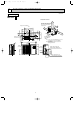
OB280-1.qxp 7 02.12.19 11:15 AM Page 6 OUTLINES AND DIMENSIONS Unit: mm OUTDOOR UNIT MXZ-18TV - E1 MXZ-18TV - E2 Even if the right / left sides or back side are vacant, the top has to be at least 100mm unobstructed. Bolt pitch for installation 500 m or 16 23 800 113 40 330 300 Air out 17 45.4 34 Air in Drainage hole {33 69 m or more more 17 34 155 152 43.6 347.
02.12.19 11:15 AM WIRING DIAGRAM MODELS MXZ-18TV- 3 2 1 CN602 ELECTRONIC CONTROL P.C. BOARD CN664 CN772 21S4 RESISTOR RESISTOR EXPANSION VALVE A,COIL EXPANSION VALVE B,COIL REVERSING VALVE SOLENOID COIL COMPRESSOR FAN MOTOR DISCHARGE TEMP. THERMISTOR DEFROST TEMP. THERMISTOR EVAPORATOR TEMP. THERMISTOR GAS PIPE TEMP.
OB280-1.qxp 02.12.19 11:15 AM 9 Page 8 REFRIGERANT SYSTEM DIAGRAM MXZ-18TV - E1 MXZ-18TV - E2 Unit:mm Discharge temperature thermistor R.V. coil heating ON cooling OFF Compressor Refrigerant flow in cooling Refrigerant flow in heating {8 Muffler {16 Stop valve (with service port) Indoor Unit B Indoor Unit A Stop valve (with service port) Gas pipe temperature B thermistor Muffler 4-way valve {12 Gas pipe temperature A thermistor Capillary tube {2.4✕{0.
02.12.19 11:15 AM 10 Page 9 PERFORMANCE CURVES The standard data contained in these specifications apply only to the operation of the air conditioner under normal conditions, since operating conditions vary according to the areas where these units are installed. The following information has been provided to clarify the operating characteristics of the air conditioner under the conditions indicated by the performance curve.
OB280-1.qxp 02.12.19 11:15 AM Page 10 10-2. Capacity and input correction by inverter output frequency (OUTDOOR UNIT:MXZ-18TV) NOTE 1 : Inverter output frequency : COOL 55Hz,HEAT 80Hz NOTE 2 : The dotted line on graphs connects the frequency range in normal operation shown by the full line and the frequency in test run shown by the point. 1. 07-class unit in single operation Total input Capacity Total input Capacity 1.5 1.5 1.5 1.5 1.0 1.0 1.0 1.0 0.5 0.5 0.5 0.
OB280-1.qxp 02.12.19 11:15 AM Page 11 10-3. Outdoor low pressure and outdoor unit current 1. 07-class unit in single operation (OUTDOOR UNIT : MXZ-18TV) NOTE:The unit of pressure has been changed to MPa on the international system of units(SI unit system). The converted score against the traditional unit system can be gotten according to the formula below. f • G) 1(MPa • G) =10.2(kgf/f (1) COOL operation 1Both indoor and outdoor units are under the same temperature/humidity condition.
OB280-1.qxp 02.12.19 11:15 AM Page 12 2. 09-class unit in single operation (OUTDOOR UNIT : MXZ-18TV) NOTE:The unit of pressure has been changed to MPa on the international system of units(SI unit system). The converted score against the traditional unit system can be gotten according to the formula below. f • G) 1(MPa • G) =10.2(kgf/f (1) COOL operation 1Both indoor and outdoor units are under the same temperature/humidity condition.
OB280-1.qxp 02.12.19 11:15 AM Page 13 3. 12-class unit in single operation (OUTDOOR UNIT : MXZ-18TV) NOTE:The unit of pressure has been changed to MPa on the international system of units(SI unit system). The converted score against the traditional unit system can be gotten according to the formula below. f • G) 1(MPa • G) =10.2(kgf/f (1) COOL operation 1Both indoor and outdoor units are under the same temperature/humidity condition.
OB280-1.qxp 11 02.12.19 11:15 AM Page 14 MICROPROCESSOR CONTROL INVERTER MULTI SYSTEM CONTROL MXZ-18TV - E1 MXZ-18TV - E2 Output signal Input signal Compressor power factor Indoor unit microprocessor Compressor primary current Compressor secondary current Outdoor unit control microprocessor Drive circuit SSR61 Transistor module Fin temperature thermistor RT67 Comp. Discharge temperature thermistor RT61 Gas pipe temperature thermistor RT66 x 61 x 62 R. V.
OB280-1.qxp 02.12.19 11:15 AM Page 15 11-1.LEV control Linear expansion valve (LEV) is controlled by "Thermostat ON" commands given from each unit. LEV opening Opening before stop ➝ 500 pulse in 15 minutes COOL : 5 pulse (full closed) HEAT : 59 pulse (slightly opened) Indoor unit status Stop of all indoor unit When outdoor unit is operating, some indoor unit stops and some operates. When the outdoor unit operation (When the other indoor unit operate): 5 pulse. When outdoor unit stops.
OB280-1.qxp 02.12.
OB280-1.qxp 02.12.19 11:15 AM Page 17 (3) LEV opening correction by discharge temperature When LEV correction output is 0 pulse by the suction super heat at cool or dry operation, or dry operating, correct LEV is corrected according to the following table. The target discharge temperature is determined according to frequency zone and number of operation unit of the compressor. COOL, DRY HEAT Operation frequency Number of operating unit. Number of operating unit.
OB280-1.qxp 02.12.19 11:15 AM Page 18 11-5.Discharge temperature protection control This protection controls the compressor ON/OFF and operation frequency according to temperature of the discharge temp. thermistor. (1) Compressor ON/OFF When temperature of the discharge temp. thermistor exceeds 116;, the control stops the compressor. When temperature of the discharge temp. thermistor is 80; or less, the controls starts the compressor.
OB280-1.qxp 02.12.19 11:15 AM 12 Page 19 TROUBLESHOOTING 12-1. Cautions on troubleshooting 1. Before troubleshooting, check the following: 1) Check the power supply voltage. 2) Check the indoor/outdoor connecting wire for mis-wiring. 2. Take care the following during servicing. 1) Before servicing the air conditioner, be sure to first turn off the remote controller to stop the unit, and then after confirming the horizontal vane is closed, turn off the breaker and / or disconnect the power plug.
OB280-1.qxp 02.12.19 11:15 AM Page 20 Troubleshooting check table LED 1 (red) Lighting LED 2 (yellow) Lighting Error mode Normal Symptom: Outdoor unit does not operate.
OB280-1.qxp 02.12.19 11:15 AM Page 21 Symptom: Oudtoor unit operates (The compressor operates at reduced frequency) Indication Abnormal point Detecting method LED 1 (red) LED 2 (Yellow) Once Lighting Current protection When the outdoor unit input current exceeds 15.5A. Twice Lighting Overload protection When the compressor load exceed the specified value.
OB280-1.qxp 02.12.19 11:16 AM Page 22 Outdoor unit does not operate. (LED display: display OFF) A Check of power supply Start Check the connecting of main circuit parts . Turn on power supply Is there voltage of 230V AC in the power supply terminal block? No Check the power supply cable. Yes Is there voltage of 325V DC across the smoothing capacity? No Is there voltage of 230V AC across the input terminal part in the diode module (DS61)? Yes Replace the outdoor electronic control P. C. board.
OB280-1.qxp 02.12.19 11:16 AM Page 23 The cooling operation or heating operation does not operate. (LED display: Both LED1 and LED2 lighting) C Check of R. V. coil • When heating operation does not work. Start 1. Disconnect the lead wire leading to the compressor. 2. Turn on power supply to the indoor and outdoor unit, three minutes later EMERGENCY OPERATION (HEAT operation) starts.
OB280-1.qxp 02.12.19 11:16 AM Page 24 • When cooling, heat exchanger of non-operating indoor unit frosts. • When heating, non-operating indoor unit get warm. D Check of LEV LED display: Start LED1 Lighting 6 time LED2 Lighting Goes out Turn on power supply to the outdoor unit after checking LEV coil is mounted to the LEV body securely.
OB280-1.qxp 02.12.19 11:16 AM Page 25 • When thermistor is abnormal. (When the LED display is a table below.) F Check of outdoor unit thermistor Start Disconnect the connector in the outdoor electronic control P. C. board (see below table), and measure the resistance of thermistor to check whether the thermistor is normal or not. Abnormal Replace the thermistor Normal Reconnect the connector (CN661, CN663 and CN664) and disconnect the lead wire leading to the compressor.
OB280-1.qxp 02.12.19 11:16 AM Page 26 H The other cases 1 Indoor unit dose not operate. (difference modes) • When you try to run two indoor unit simultaneously, one for cooling and the other for heating, the unit which transmits signal to the outdoor units earlier decides the operation mode. The other unit indicates as shown in the figure below. • When the above situation occurs, set all the indoor units to the same mode, turn OFF the indoor units, and then turn them back ON.
02.12.19 11:16 AM Page 27 TEST POINT DIAGRAM AND VOLTAGE MXZ-18TV - E1 ,MXZ-18TV - E2 Room B Linear expansion valve (LEV) 12V DC pulse wave Linear expansion valve (LEV) 12V DC pulse wave Room A Outdoor fan Hi 12V DC Outdoor fan Lo 12V DC Fin temperature thermistor (RT67) Current Limit Relay 12V DC Defrost temperature thermistor (RT62) Discharge temperature thermistor (RT61) Evaporation temperature thermistor (RT63) R.V.
OB280-1.qxp 02.12.19 11:16 AM Page 28 Noise filter P.C.board MXZ-18TV - E1 230V AC 50Hz Input 230V AC 50Hz Output Outdoor Fan Fan speed “Hi” 230V AC Outdoor Fan Fan speed “Lo” 230V AC Reversing valve 230V AC MXZ-18TV - E2 230V AC 50Hz Input 230V AC 50Hz Output Outdoor Fan Fan speed “Lo” 230V AC Outdoor Fan Fan speed “Hi” 230V AC FUSE(F911)AC250V 1A R.V.coil 230V AC 28 FUSE(F912)AC250V 3.
OB280-1.qxp 02.12.19 11:16 AM 13 Page 29 DISASSEMBLY INSTRUCTIONS MXZ-18TV - E1 ,MXZ-18TV - E2 OUTDOOR UNIT OPERATING PROCEDURE PHOTOS 1. Removing the top panel ~ back panel (1) Remove the screws fixing the top panel and remove it. (Photo 1) (2) Remove the screw fixing the service panel, next pull down the service panel and remove it from the cabinet. (Photo 2) (3) Remove the screws fixing the front cover and remove it. (4) Remove the inside and outside connection electric wire.
OB280-1.qxp 02.12.19 11:16 AM Page 30 OPERATING PROCEDURE PHOTOS 5. Removing the 4-way coil (1) Remove the top panel, front cover and service panel. (2) Remove the inside and outside connection electric wire, next remove the back panel. (3) Remove 4-way coil and disconnect the noise filter P.C. board connectors CN912 Photo 5 6. Defrost, Discharge temperature thermistor (1) Remove the top panel, front cover, service panel.
OB280-2.qxp 02.12.19 11:18 AM Page 31 OPERATING PROCEDURE PHOTOS 9. Remove the compressor (1) Remove the top panel, front cover, service panel. (2) Remove the inside and outside connection electric wire, next remove the back panel. (3) Remove the inverter assembly. (4) Can have the service of compression, 4-way and other refrigerant circuit.. (5) Remove then the part (four places) which welds it when you leave 4-way.
OB280-2.qxp 14 02.12.19 11:18 AM Page 32 PARTS LIST 14-1. OUTDOOR UNIT FUNCTIONAL PARTS MXZ-18TV - E1 14 13 MXZ-18TV - E2 1 12 2 11 10 3 9 4 5 6 Symbol No. Parts No. Parts Name in Wiring Diagram 1 2 3 4 T2W E87 308 FIN TEMPERATURE THERMISTOR T2W E45 447 DIODE STACK 7 8 Q'ty / unit MXZ-18TV- E1 MXZ-18TV- RT67 1 1 DS61, DS62 2 2 L 1 1 1 1 M21 68K 337 REACTOR T2W E87 471 CONNECTOR POST ASSY 5 T2W E87 424 NOISE FILTER P.C. BOARD T2W G04 424 NOISE FILTER P.C.
OB280-2.qxp 02.12.19 11:18 AM Page 33 14-2. OUTDOOR UNIT STRUCTURAL PARTS MXZ-18TV - E1 MXZ-18TV - E2 14 13 15 12 1 11 16 10 17 18 2 3 4 5 6 7 8 9 Part numbers that are circled are not shown in the illustration. Symbol No. Parts Name Parts No.
OB280-2.qxp 15 02.12.19 11:18 AM Page 34 OPTIONAL PARTS 15-1. Different-diameter pipe Unit : mm (inch) MXZ-18TV Model name Model code Connected pipes diameter (mm) For differentdiameter pipes MAC-454JP 51H-454 {9.52 — {12.7 (3/8) (1/2) Length A Length B Length C {9.52 (3/8) {12.
OB280-2.qxp 02.12.
OB280-2.qxp 02.12.20 9:24 AM Page 36 HEAD OFFICE: MITSUBISHI DENKI BLDG.,2-2-3, MARUNOUCHI, CHIYODA-KU, TOKYO100-8310, JAPAN C Copyright 2001 MITSUBISHI ELECTRIC ENGINEERING CO.,LTD. Distributed in Dec. 2002. No.OB280 REVISED EDITION-A 16 Reprinted in Dec. 2001 No.OB280 5 Reprinted in Dec. 2001 No.OB280 50 Distributed in Mar. 2001. No.OB280 49 Made in Japan New publication, effective Dec. 2002 Specifications subject to change without notice.