
Service manual


30
OPERATING PROCEDURE
PHOTOS
5. Removing the 4-way coil
(1) Remove the top panel, front cover and service panel.
(2) Remove the inside and outside connection electric wire, next
remove the back panel.
(3) Remove 4-way coil and disconnect the noise filter P.C. board
connectors CN912
6. Defrost, Discharge temperature thermistor
(1) Remove the top panel, front cover, service panel.
(2) Remove the inside and outside connection electric wire, next
remove the back panel.
(3) Remove the connector CN663 on inverter P.C. board.
(4) Remove the defrost thermistor and remove the discharge
temperature thermistor on the compressor. (Photo 5, 6)
7. Fin temperature thermistor
(1) Remove the top panel, front cover, service panel.
(2) Remove the inside and outside connection electric wire, next
remove the back panel.
(3) Remove all the connectors the lead wire and the earth wire
on the electronic control P.C. board.
(4) Remove the compressor relay connector. (Photo 3)
(5) Remove the two screws fixing the heat sink, and pull up the
inverter P.C. board. (Photo 4)
(6) Remove the screws fixing the transistor module. (Photo 4)
(7) Remove the screws the fin temperature thermistor, and
remove it. (Photo 7)
8. Removing the fan motor
(1) Remove the top panel, front cover.
(2) Remove the fan motor connectors (CN911) on the noise fil-
ter P.C. board.
(3) Remove the propeller fan.
(4) Remove the screws fixing the fan motor and remove it.
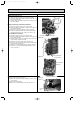
Photo 5
Photo 6
Photo 7
Photo 8
Discharge temperature thermistor
Defrost thermistor
Inverter board
Fin temperature
thermistor
Screws of fan motor
Fan motor
Propeller
fan
OB280-1.qxp 02.12.19 11:16 AM Page 30