
Installation manual

4
5
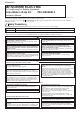
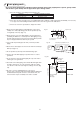
4 Wiring
a) Connect the blue connector of the 2-wire cord
to CNP on the noise filter board inside the
control box.
b) Insert the white connector of the 2-wire cord
into CN4F on the indoor P.C. board.
Since a connector has been inserted into both
CNP and CN4F before shipment, they must
be removed.
c) When wiring is complete, fasten the remaining
cords with the band (small) 3.
2-wire cord
From drain pump
2-wire cord
From float switch
from float switch
C
N
P
Indoor P.C. board
CN4F
White
Noise filter board
from drain pump
Blue
2-wire cord
2-wire cord
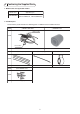
Photo 4-1
Fig. 4-1
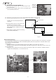
4-1. Passing the pump wires (Photo 4-1)
a) Pass the 2-wire cord (with a blue connector) through the hole
shown in the photo.
b) Pass the 2-wire cord (with a white connector) through the pipe
sensor and LEV lead wire hole.
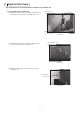
When fastening lead wires
Power wires and low-voltage wires are separately bundled inside the control box to reduce noise interference. Lead wires
from the Drain Water Lift-Up Kit also need to be bundled separately. Follow the steps below to hold them and the lead
wires inside the control box together.
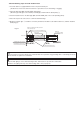
(1) Power wires
* Feed the lead wires from the drain pump through the wire saddle as shown with "A" in Photo 4-2.
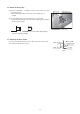
* Bundle the excess lead wires from the drain pump, and clip them together with a cable clip as shown in Photo 4-3.
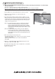
(2) Low voltage wires
* Bundle the excess lead wires from the float switch, then keep them, pipe sensor lead wires, and LEV lead wires
together with a band (small) 3 as shown in Photo 4-4.
Photo 4-3
Photo 4-4
Photo 4-2
4-2. Connecting the pump wires to the control box of the indoor unit (Fig. 4-1)