DLPTM Data Display Cube PH50 series (SXGA+ models) XL50, XL21 series (XGA models) Set-up and Installation Manual March 09, 2007 (REV 2.
Table of Contents 1. SET-UP AND INSTALLATION......................................................................................................5 1.1. Overview ...............................................................................................................................5 1.1.1. Product lineup ................................................................................................................5 1.1.2. Flowchart....................................................................
1.8.5. DIGITAL OUT ...............................................................................................................67 1.8.6. SCREEN MODE...........................................................................................................67 1.8.7. Display memory saving ................................................................................................68 1.8.8. Display memory calling/deleting ...................................................................................
.2.1. Software Installation .....................................................................................................99 4.2.2. Connecting ...................................................................................................................99 4.2.3. Dipswitch setting...........................................................................................................99 4.2.4. Starting the application .............................................................................
1. Set-up and installation 1.1. Overview 1.1.1. Product lineup Lineup Resolution Lamp Access PH50 series SXGA+ Changer Changer XL50 / ( XL21 )(*1) series XGA Front Rear Front Rear Front Single Rear Screen size 50” 67” – VS-67PHF50U VS-50PH50U VS-67PH50U VS-50XLWF50U VS-67XLWF50U VS-50XLW50U VS-67XLW50U (VS-50XLW20U) (VS-67XLW20U) VS-50XLF50U VS-67XLF50U (VS-50XLF20U) VS-50XL50U VS-67XL50U (VS-50XL21U, VS-50XL20U) (VS-67XL21U, VS-67XL20U) (*1) Parenthesized products are XL21 series. 1.1.2.
1.2. Cube installation 1.2.1. Safety precaution • This product requires a special installation to prevent falling or toppling. This should be done by installation specialists. • Be sure to read this manual and the user’s manual for your safety before starting assembly or installation. • Be sure to use supplied accessories for assembly or installation. • Attach all the screws and fixtures specified in this manual securely.
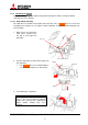
1.2.3. Input board installation (optional) When using the optional input board, install it into the product according to the following steps. In Front , a slot for the board is located inside the cube. Open the screen unit before installation according to the chapter 1.2.7 on page 21. When you attach it, be sure to turn off the main power switch. 1. Remove a panel cover on the control panel by removing 6 screws at the positions shown in the figure. 2.
1.2.4. Unlocking (for XL21 ) Surely release following locks before turning on the main power switch. Turning on without releasing may cause damage. 1.2.4.1. Color wheel unlocking The color wheel is located on the optical unit inside the cube. In Front , open the screen unit according to the chapter 1.2.7 on page 21 before unlocking. Turning on without unlocking may cause damage. 1. Make sure a key slot on the color wheel cushion faces the top as you begin the procedure.
1.2.4.2. Lamp cushion removing (for Changer ) Remove a lamp cushion before turning on the main power switch. Turning on without removing may cause smoking and catching fire. • It should be remembered to lock the lamp cover after removing. If you neglect to lock it, the lamp changer may not work correctly. Lamp cushion Lock Lamp cover Caution Before shipment, be sure to insert the cushion in the reverse order of removing (chapter 2.5.3, on page 85).
1.2.5. Cube stacking (for Rear ) 1.2.5.1. Assembling the base stands and cubes 1. Assemble base stands. 2. Adjust level adjusters to make the base stand both level and plumb by means of a spirit level. Base stands 3. 4. Loosen 4 screen-fixing screws per unit shown with arrow lines in the right figure with an Allen wrench (5 mm) to remove the screen units from all cubes to be installed. (This applies to 50” , which is supplied with the screen fitted).
8. 9. Place the next bottom row cube on the base stand and fix it in the same way. Join right and left cubes at 4 points with supplied hexagon socket head bolts, spring washers and flat washers. 10. Place cubes for the upper row on the assembled units. 11. Fix them vertically and horizontally at 4 points each with supplied hexagon socket head bolts, spring washers and flat washers. 12. Stop up the holes on both sides with supplied joint hole seals, which holes are not used for a display wall.
1.2.5.3. Fixing to the wall and floor You don’t have to attach the lower door in this chapter since picture outlines have yet to be adjusted as explained in the next chapter. After the picture outline adjustment, attach the door in the reverse order of detaching. 1. Attach floor-fixing brackets on 4 level adjusters below the base stand and fix them to the floor with anchor bolts. 2. Fix the upper back part of the display wall to the back wall with wall-fixing brackets as shown in the following figure.
1.2.6. Cube stacking (for Front ) Caution Take heed of appropriate surrounding space for ventilation (except rear surface) such as not to pool the hot air on the top of the display walls so that the ambient temperature doesn’t exceed the product environmental requirements. 1.2.6.1. Tape peeling off (for 67” ) The screen-holding arms in both sides are taped at each end for transportation. Peel them off before installation. Tape Screenholding arm Tape REV 2.
1.2.6.2. Screen detaching For 50” which is supplied with the screen fitted, the screen unit should be detached before installation. (For 67” , the screens are provided separately.) 67” : Screen attaching/detaching work should be done by two or more people. Be careful not to trap your fingers when you slide its arms during detaching/attaching work. 1. 50” : Remove two screen-fixing bolts (M6 – 45mm, gold hexagon socket). Caution Before shipment, be sure to tighten the bolts (see chapter 2.5.4, on page 86).
1.2.6.3. Ventilation To ensure a proper airflow for cooling, you need to block some vents as the following figures. Should be blocked Exhaust Exhaust Panel 1 Panel 2 (From rear) (From rear) Panel 3 Panel 4 Exhaust Exhaust Panel 1 Panel 2 Top row Panel 3 Panel 4 Bottom row (From rear) (From rear) Base stand Intake Vents to be blocked For 67” , 50” Changer Vents to be blocked Airflow concept Intake External AC fans (occasional) For 50” Single 1.2.6.3.1. For 67” , 50” Changer 1.
1.2.6.3.2. For 50” Single According to circumstances, attach the optional external AC fans (JC-AF115R or JC-AF230R) on the intake vents in the bottom row (see “External AC fan attaching” on page 17). • Prepare openings on base stands to ventilate. • Keep enough base stand height not to inhale a coat of dust on a floor from the intake vents. 1. 2. To block the bottom row, detach the bottom duct cover from inside the cube and attach it on the bottom of the duct.
External AC fan attaching (occasional) When 4-high configuration with 50” Single , attach the optional external AC fans (JC-AF115R or JC-AF230R) on intake vents. Even in 3-high configuration, attach the AC fans as well, when spaces are narrower than 50cm to the ceiling and 10cm to the wall behind. Narrow spaces tend to rise the cube internal heat. Be sure this work is only for the cubes in the bottom row. 1.
1.2.6.4. Assembling base stands and cubes 1. Assemble base stands. 2. Adjust level adjusters to make the base stand both level and plumb by means of a spirit level. Base stands Level adjusters 3. 4. 5. 6. 7. 8. 9. Place a cube on the base stand. Caution Do not grip the screen-holding arms to lift up a cube cabinet. It may cause breakage. Fix the cube at 4 points with supplied hexagon socket head bolts, spring washers and flat washers.
11. Press down the slide lock levers in both sides to unlock, and draw the screen-holding arms till locked. 67” : The levers can be unlocked respectively. Screen-holding arm Slide lock lever (Inside the arm) 12. Reinstall the screen unit in its original cabinet. Put the pins inside the screen unit on the retainers at the top of the screen-holding arms, following which make the screen upright. Make sure it will be locked securely. 67” : Screen attaching/detaching work should be done by two or more people.
3. 4. 5. 6. For horizontal adjustment: 50” : Loosen two screws in the right screen guide to adjust its horizontal position and fix them. 67” : Loosen the screw in the bottom screen guide to adjust its horizontal position and fix it. The screen guide has punch marks at the adjustable range (+/- 2mm) and its center. For vertical adjustment: Loosen two screws each in the left and right screen guides to adjust their vertical positions and fix them.
1.2.7. Screen open/close (for Front ) Cabling or lamp replacement, etc. requires opening the screen unit. Be careful not to trap your fingers during the work. The open/close should be Cube unit performed on a one-by-one basis in a display wall so as not to shift the center of gravity much. In particular, 67” may cause topple down due to wide shifting of the center of gravity.
3. Pull up the bottom of the screen unit to rotate 90 degrees with pushing flip-up lock levers located inside the screen unit in both sides. 67” : The levers can be unlocked respectively. Be careful not to push the Push adjacent screen-detaching lever. (Screen-detaching lever) Flip-up lock lever (inside the screen unit) 1.2.7.2. Screen closing Be careful not to trap your fingers during the work. 1. Push down the bottom of the screen slowly till locked. 2.
1.3. Connecting 1.3.1. Control signal connection An external controller such as a personal computer etc. can control cubes through RS-232 format communication. In the case of a display wall, connect the external controller to a MASTER cube set by dipswitch (chapter 1.4.2, on page 28) with RS-232 cross cable, and connect CONTROL IN and CONTROL OUT terminals between cubes with supplied control cables. Do not connect to a loop.
1.3.2.2. For other than daisy chain Connecting with a multiple-output device, an enlarged image can be displayed as well as daisy chain connection. Supplied control cables External controller Multiple-output ID 1 MASTER ID 2 SLAVE ID 3 SLAVE ID 4 SLAVE device Input image Connecting with a multiple-output device (example) 1.3.3. Internal cabling (for Front ) Run cables through the holes located on both sides and top/bottom.
1.4. Initial set up 1.4.1. Menu operation 1.4.1.1.
1.4.1.2. Operation mode This product has two operation modes: “normal mode” and “advanced mode”. Use the normal mode in usual operation. Switch to the advanced mode when you set up or adjust the product. Two modes can be switched by [NORMAL] button when there is no adjustment menu on screen. 1.4.1.2.1.
1.4.1.3. Basic menu operation Adjustments should be conducted with the remote control in advanced mode. (You can also use the adjustment software, “Wallaby” (chapter 4, on page 99)). • [POWER ON] button: To turn on after main power switch on. • [MENU1] button: To display the input memory menus. • [MENU2] button: To display the display memory menus while the input board is attached. • [MENU2] button (press and hold): To display the system memory menus. • Up/down button: To select menu items.
1.4.2. Dipswitch setting Before turning on the main power switch, set the dipswitch correctly according to a system configuration (see “1.3 Connecting” on page 23). The set ID can be set up to 64 (see “1.5.1.14 EXTENDED ID” on page 41). Be sure to turn off the main power switch if you change the setting in the middle of the operation. Turning on the main power switch will renew the setting. OFF ON 1 2 3 4 RC 5 6 7 8 ID4 RESERVED MASTER ID5 ID3 ID2 ID1 No.
1.4.3.2. 6-axis adjustment 1.4.3.2.1. Release the lock screws Before 6-axis adjustment, release locks in the adjuster. Loosen 4 locking screws with an Allen wrench (2mm) and 5 fixing screws with an Allen wrench (4mm). 1.4.3.2.2. 4 locking screws 5 fixing screws When adjusting with motorized adjustment tool, S-AXL50E Slide switch Rotary Dial Attaching 1. Set the rotary dial in the upper unit of the adjustment tool according to the product (chapter 3.8.4.
6. 7. 8. Make sure that latches on the units are released before the attaching the units. Attach the units on the adjuster in order of the lower and upper unit. Push the two latches each till click to fix the units. Latches 9. Latch Release Lock Latches Lower unit Upper unit Connect the other end of the cube-connecting cable with a connector inside the cube as following figures. The cable can be connected under operating conditions. For Front For Rear Connector (in the circuit box) 10.
Adjustment Perform the picture outline adjustment with remote control. 1. Make sure to release the locks in the adjuster (chapter 1.4.3.2.1 on page 29). 2. Display the internal crosshatch pattern for picture outline adjustment by pressing [TEST] button twice in advanced mode. (Refer to the chapter 1.4.1.2 on page 26). 3. Press-and-hold [MENU2] button to display the system memory menu. 4. Select MECH ALIGNMENT in MAINTENANCE in the system menu. 5.
1.4.3.2.3. When adjusting by manual Perform the picture outline adjustment with an Allen wrench (5mm).
1.4.3.2.4. Adjusting procedure 1. After making an image size smaller than the outline of screen with the zoom axis, adjust Tilt, V position and H position so that upper and lower spaces and right and left spaces will be almost equalized respectively. A=A’, B=B’ A A’ B B’ 2. Correct the horizontal keystone distortion, and adjust the image position to the center of the screen with “H position”. Correct the horizontal keystone distortion. 3.
1.4.3.3. Mirror adjustment 1.4.3.3.1. Parallelogram distortion correction When a parallelogram distortion cannot be corrected with the 6-axis adjuster, correct it according to the following procedure. 1. Allign top, bottom and right lines of the crosshatch pattern with the screen edge by the 6-axis adjustment. Parallelogram distortion 2. Rear : Loosen screws in the rear panel and upper door. And then open the upper door and lift the rear panel to remove. Front : Open the screen unit (chapter 1.2.7.
3. Loosen a mirror fixing screw located in the right seen from the rear. (Or in the left seen from the front in Front .) Mirror fixing screw (rear) For 50” XL21 (Seen from top) Mirror fixing screw (side) For other models 4. (Mirror adjusting screw) Turn the mirror adjusting screw.
1.4.3.3.2. Pincushion distortion correction (for 50” ) When pincushion distortion appears and it cannot be corrected with 6-axis adjuster, you can correct it according to the following procedure. Even after cube stacking, you can reach the following Pin cushion screws for the correction through holes in the upper cube. Detach a screen from the upper cube to access the screws. Note: In XL21 Rear , this correction should be done before cube stacking. You cannot access the adjusting screws after the stacking.
1.5. System memory setting Set the system memory as shown below to suit a configuration. The parameters are effective for all input memories and display memories. Press and hold [MENU2] button to display the system memory menus. You can exit the menu by [ESC] button. 1.5.1. System set up 1.5.1.1. LAMP POWER Used to set brightness mode. The initial setting is NORMAL. BRIGHT mode can make cubes brighter. The lamp life becomes shorter than NORMAL mode. [Procedure] 1.
1.5.1.5. START MEMORY This adjustment is normally unnecessary. Used to designate a display memory number that is loaded at start-up. The initial setting is OFF. To display a designated image source, set a registered display memory number (chapter 1.8.7, on page 68), or a registered input memory number when the main input port is selected. If it is set OFF, the product starts up with a last loaded memory. [Procedure] 1. Select START MEMORY in MISC FUNCTION in the system menu. 2. Set 1 – 256 or OFF. 1.5.1.6.
1.5.1.8. BAUD RATE Used to select the transmission speed of RS-232 in accordance with an external controller setting. The initial setting is 19200 (19,200bps). You can select 9,600bps or 19,200bps. [Procedure] 1. Select BAUD RATE in MISC FUNCTION in the system menu. 2. Set 9600 or 19200. 1.5.1.9. SYSTEM SYNC Used to set a vertical synchronizing frequency in accordance with a moving pictures signal to be mainly displayed. The initial setting is 60 (60Hz). Set 60Hz for NTSC signal or 50Hz for PAL signal.
1.5.1.11. INDICATION This adjustment is normally unnecessary. Used to set how to indicate the status information. 1.5.1.11.1. WARNING (for Changer ) This is to set the indication of a warning mark on screen to induce to replace the spare lamp after auto-lamp changing or pre-announcement of the changing (“2.1.3.5 Warning indication”, on page 80). • OFF: No indication. • MESSAGE, ☀: To display both pre-announcement of auto-lamp changing and a warning mark to induce to replace the spare lamp.
1.5.1.12. AUTO POWER ON Used to set automatic turning on when the main power is supplied. The initial setting is OFF. • ON: Automatic turning on when the main power is supplied. • OFF: When the main power is supplied, the product takes over the last memory status. For instance, it becomes stand-by state if the main power was turned off in stand-by state. Likewise, if it was turned off in the state of power on, it automatically turns on. [Procedure] 1.
1.5.1.15. CABLE LENGTH (for PH50 and XL50 ) Used to set it according to a digital cable length of image inputs. The initial setting is NORMAL. Set LONG when image noise is noticeable due to a transmission attenuation through a long digital cable such as over 5 meters. As needed, CUSTOM menu can be selected for more detailed adjustment. [Procedure] 1. Select CABLE LENGTH in MISC FUNCTION in the system menu. 2. Select DIGITAL or S.DIGITAL according to the input port. 3. Set NORMAL, LONG or CUSTOM. 4.
1.5.1.18. LAMP CHANGE (for Changer ) 1.5.1.18.1. CALIBRATION This adjustment is normally unnecessary. It is automatically set at auto-lamp changing (chapter 2.1.3, on page 78). It adjusts the lamp position optimally to maximize the brightness. [Procedure] 1. Select CALIBRATION in LAMP CHANGER in MAINTENANCE in the system menu. 2. Press [ENTER] button in reply to “SET OK?” message to adjust the lamp to the suitable position automatically. 1.5.1.18.2. CHANGE MODE This adjustment is normally unnecessary.
1.5.2. Color balance adjustment You can adjust luminance and tint between each screen of a display wall. In principle, they should be adjusted according to (3) CSC adjustment. However, follow (2) BLACK LEVEL, (4) WHITE BALANCE and (5) GRADATION adjustments, if necessary. After that, set TARGET COLOR and SENSOR to maintain the uniformity over the long term.
1.5.2.3.3. By manual Seeing actual colors on screens, they can be adjusted by manual. Adjusted CSC values can be saved in the memory of either CSC1 or CSC2. [Procedure] 1. Press [TEST] button three times to display the adjustment white. 2. Select CSC in MAINTENANCE in the system menu. 3. Select CSC1 or CSC2. 4. Press [R], [G] or [B] buttons to display a monochrome color to adjust. 5.
1.5.2.4. WHITE BALANCE This adjustment is normally unnecessary. The luminance and tint between screens can be adjusted in CSC. Used to adjust a color temperature. Three memories: LOW, MIDDLE and HIGH can be used to save in. [Procedure] 1. Press [TEST] button three times to display the adjustment white. 2. Select WHITE BALANCE in INSTALLATION in the system menu. 3. Select HIGH, MIDDLE or LOW. 4. Adjust R, G and B values. 1.5.2.5.
1.5.2.6. TARGET COLOR Set it after adjustment of the luminance and tint between screens. TARGET COLOR can register the adjusted CSC values, color wheel data and lamp data. When the lamp or color wheel is replaced, it can detect the replacement and automatically calculates the optimum CSC values. [Procedure] 1. Select SET TARGET COLOR in TARGET COLOR in MAINTENANCE in the system menu. 2. Press [ENTER] button in reply to “SET OK?” message. 3.
1.5.3. Image set up 1.5.3.1. COLOR MATRIX:USER This adjustment is normally unnecessary. Used to adjust the hue of RED, YELLOW, GREEN, CYAN, BLUE or MAGENTA respectively. Normally the optimum option is automatically selected depending on the type of an input signal. The color is available only when you select USER in COLOR MATRIX (on page 55 or 63) in an input memory menu. [Procedure] 1. Select COLOR MATRIX:USER in INSTALLATION in the system menu. 2.
1.5.3.3. SCALER AMP GAIN (for S.ANALOG input) This adjustment is normally unnecessary. Used to adjust the gain level of analog signal in the input board. It is effective in all input memories. Normally adjust it for each input memory by the same menu (chapter 1.7.4.3, on page 59) in input memory. [Procedure] 1. Display a full-white video signal through actual input route. 2. Select SCALER AMP GAIN in INSTALLATION in the system menu. From here, follow the same procedure as “AMP GAIN” in the previous chapter.
1.5.3.8. 3D Y/C (for COMPOSITE input) This adjustment is normally unnecessary. Used to turn on/off the three-dimensional Y/C separation circuit. The initial setting is ON. On setting can display an NTSC signal with less dot interference image in COMPOSITE input. [Procedure] 1. Select 3D Y/C in MISC FUNCTION in the system menu. 2. Set ON or OFF. 1.5.3.9. WHITE BOOST This adjustment is normally unnecessary.
1.6. Input memory setting (for the main input) Press [MENU1] button to display the input memory menus. You can exit the menu by [ESC] button. Be careful that menus for the main input are different from the ones for the input board. 1.6.1. Input port selecting Input ports can be switched while any menus or test patterns are not displayed. [Procedure] 1. Press [INPUT A] button to display the input port selecting menu. 2. Select an input port by up/down buttons and press [ENTER] button to change. 3.
1.6.3. Signal adjustment 1.6.3.1. H.POSITION, V.POSITION Used to adjust an incorrect image position so as to minimize no signal area on the upper left of the screen. [Procedure] 1. Select H.POSITION in the input memory menu. 2. Adjust the value by left/right button not to display no signal area on the left of screen. 3. Select V.POSITION in the input memory menu. 4. Adjust the value by left/right button not to display no signal area on the top of screen. 1.6.3.2.
1.6.3.4. H.SIZE, V.SIZE (for PH50 and XL50 ) This adjustment is normally unnecessary. The optimum value is automatically set in automatic input signal scanning. Used to adjust an incorrect size of an effective input image area after H.TOTAL (in ANALOG input) and H.POSITION, V.POSITION adjustment. [Procedure] 1. Select H.SIZE in the input memory menu. 2. Adjust the horizontal size of the input signal. 3. Select V.SIZE in the input memory menu. 4. Adjust the vertical size of the input signal. 1.6.3.5.
1.6.3.8. CLAMP (for ANALOG input) This adjustment is normally unnecessary. The optimum value is automatically set in automatic input signal scanning. Used to adjust a clamp pulse position and the width according to the timing of an input signal. Incorrect CLAMP setting makes whole image darkened and uneven horizontal brightness appears on the image. CLAMP is automatically set to the optimum value when you set CLAMP START=0, CLAMP WIDTH=0. [Procedure] 1. Select CLAMP START in the input memory menu. 2.
1.6.4. Image quality adjustment These adjustments are normally unnecessary. You can adjust the following items as needed. Set the same value on all cubes in a display wall. 1.6.4.1. CONTRAST Used to adjust contrast. The initial setting is 100. Be noted that an excessive image darkening deteriorates the tone characteristics of darker parts of the image. [Procedure] 1. Select CONTRAST in the input memory menu. 2. Adjust the value by left/right buttons. 1.6.4.2. BRIGHTNESS Used to adjust brightness.
1.6.5. Input memory saving The adjusted values can be saved in an input memory. The number of the memories is 128. Be sure to save when you change the values. Even if the same resolution has already registered in a memory, save the new adjusted values in another input memory if some menus such as FINE or POSITION have different values from the existing memory. [Procedure] 1. Press [ESC] button during the input memory menu displaying. In reply to “SAVE THE CHANGES?” message, press [ENTER] button.
1.7. Input memory setting (for the input board) Press [MENU1] button to display the input memory menus. You can exit the menu by [ESC] button. 1.7.1. Input port selecting Input ports can be switched while any menus or test patterns are INPUT PORT not displayed. ANALOG [Procedure] DIGITAL S.ANALOG 1. Press [INPUT A] button to display the input port selecting S.DIGITAL menu. COMPOSITE 2. Select an input port by up/down buttons and press [ENTER] Y/C button to change.
1.7.4. Signal adjustment 1.7.4.1. H.POSITION, V.POSITION Used to adjust an incorrect image position so as to minimize no signal area on the upper left of the screen. [Procedure] 1. Select H.POSITION in the input memory menu (on the 1st menu sheet). 2. Adjust the value by left/right button not to display no signal area on the left of screen. 3. Select V.POSITION in the input memory menu (on the 1st menu sheet). 4. Adjust the value by left/right button not to display no signal area on the top of screen.
1.7.4.3. AMP. GAIN (for S.ANALOG input) Used to adjust the gain level of an analog signal in the input board. Due to uneven AD converting levels of analog input, colors in each screen look different even if the CSC adjustment is appropriate. It is effective in each input memory. It cannot be adjusted when the input signal is YUV signal. [Procedure] 1. 2. 3. 4. Display a full-white signal through an actual input route. Select AMP GAIN in the input memory menu (on the 4th menu sheet).
1.7.4.5. FRAME LOCK This adjustment is normally unnecessary. The optimum value is automatically set in automatic input signal scanning. Used to set a frame lock. Set ON when frame tearing or field skips are noticeable in a moving image with 50 – 60 Hz of vertical frequency. • ON: External synchronization mode to synchronize the frame rate to the input signal. • OFF: Internal synchronization mode to convert the frame rate to an internal rate. [Procedure] 1.
1.7.4.8. H.TOTAL (for S.ANALOG input) This adjustment is normally unnecessary. The optimum value is automatically set in automatic input signal scanning. Used to adjust a total horizontal dot number of an input signal. Incorrect H.TOTAL value makes vertical striped noises or jitter noises on an image, or whole effective area cannot be displayed even after the image position adjustment. [Procedure] 1. Select H.TOTAL in the input memory menu (on the 3rd menu sheet). 2.
1.7.4.11. SYNC SELECT (for S.ANALOG input) This adjustment is normally unnecessary. The optimum value is automatically set in automatic input signal scanning. Used to select sync on green setting. The initial setting is AUTO. HD/VD may make FINE easier to match in 5-line input (separate sync). Set SOG (sync on green) for 5-line (separate sync) or 4-line (composite sync) input with sync on green signals since this clamp pulse on the green channel cannot be adjusted.
1.7.5. Image quality adjustment These adjustments are normally unnecessary. You can adjust the following items as needed. Set the same value on all cubes in a display wall. 1.7.5.1. CONTRAST Used to adjust contrast. The initial setting is 100. Be noted that an excessive image darkening deteriorates the tone characteristics of darker parts of the image. [Procedure] 1. Select CONTRAST in the input memory menu (on the 2nd menu sheet). 2. Adjust the value by left/right buttons. 1.7.5.2.
1.7.5.5. ASPECT-RATIO The optimum value is automatically set in automatic input signal scanning. It is available when SCREEN MODE (chapter 1.8.6, on page 67) in the display memory menu is set NORMAL or TRIMMING. • 4:3 : The image is displayed at the aspect ratio of 4:3. • 5:4 : The image is displayed at the aspect ratio of 5:4. • 16:9 : The image is displayed at the aspect ratio of 16:9. [Procedure] 1. Select ASPECT-RATIO in the input memory menu (on the 2nd menu sheet). 2. Select 4:3, 5:4 or 16:9. 1.7.5.6.
1.7.6. Input memory saving The adjusted values can be saved in an input memory. The number of the memories is 128. Be sure to save when you change the values. Even if the same resolution has already registered in a memory, save the new adjusted values in another input memory if some menus such as FINE or POSITION have different values from the existing memory. [Procedure] 1. Press [ESC] button during the input memory menu displaying. In reply to “SAVE THE CHANGES?” message, press [ENTER] button.
1.8. Display memory setting (for the input board) Used to set an image position and expansion ratio for the input board signals to display on a display wall. Press [MENU2] button to display the display memory menus. You can exit the menu by [ESC] button. There is no need to register the display memory when the input board is not attached. In this case, the display memory menu is not displayed. 1.8.1. INPUT MEMORY Used to designate an input image signal to be displayed. [Procedure] 1.
1.8.4. DISPLAY This adjustment is normally unnecessary. The optimum value is automatically renewed when H./V. DISPLAY POS. are changed. Used to designate a display area on screen by manual. It can tweak an unmatched image linkage between screens. • H.POSITION: The horizontal starting position of the display area. • V.POSITION: The vertical starting position of the display area. • H.SIZE: The horizontal display size. It can erase a noise on a side of images. • V.SIZE: The vertical display size.
1.8.7. Display memory saving The adjusted values can be saved in a display memory. The number of the memories is 256. For the saving, an input memory number is required in INPUT MEMORY menu (chapter 1.8.1, on page 66). If the input memory has not been registered, save the input memory in advance (chapter 1.7.6, on page 65). [Procedure] 1. Press [ESC] button during the display memory menu displaying. In reply to “SAVE THE CHANGES?” message, press [ENTER] button.
1.9. Setting as daisy chain connection (for the input board) The adjustment procedure of a daisy-chained display wall is shown in the following flowchart. Adjust the first cube, which takes an input signal from an external device, following which, adjust other downstream cubes that require a digital image signal from the first cube.
4. Set the position and expansion ratio (“1.8.2 H.DISPLAY POS, V.DISPLAY POS” on page66) again to fit a configuration in reference to the following setting sample in left side. Check the displaying to be as the example in right side. Image signal 5. 6. 7. H=1/2 V=1/2 H=2/2 V=1/2 H=1/2 V=2/2 H=2/2 V=2/2 A Set SCREEN MODE (chapter 1.8.6, on page 67) as needed. Save the display memory (chapter 1.8.7, on page 68) of each screen in a different memory number from a previous saving.
2. Regular maintenance 2.1. Lamp replacement This product is equipped with lamp(s) to project images. The lamp is a consumable. It may burn out or the brightness may decrease during operation. In such cases, replace the lamp with a new one as soon as possible. When the lamp doesn’t illuminate any more, a blue light blinks on the screen and error indicator in the control panel shows “1.” (chapter 3.5, on page 91).
2.1.2. Procedure 2.1.2.1. For Single 1. Rear : Hold down the handles by the fingers and pull the lower door to open. Front : Open the screen unit (chapter 1.2.7.1, on page 21). Lower door Handles 2. Turn off the main power switch and unplug the power cord from the wall outlet. 3. Loosen the two lamp fixing screws. Lamp fixing screws 4. Hold the handle and pull out the lamp. • Be sure to grip the handle with one hand and hold the lamp with the other hand to pull it out safely.
6. Tighten the two lamp fixing screws. Lamp fixing screws 7. Rear : Close the lower door. Front : Perform “Dust filter cleaning” (chapter 2.4.3, on page 83) as needed, and close the screen unit (chapter 1.2.7.2, on page 22). 8. After the replacement, perform “Condenser lens adjustment” (chapter 2.2, on page 81), “Color balance adjustment” (chapter 1.5.2, on page 44) or “Picture outline adjustment” (chapter 1.4.3, on page 28) as needed.
2.1.2.2. For Changer With HOT EXCHANGE menu (chapter 1.5.1.18, on page 43), you can set the allowance the replacement while main lamp lighting. In the FORBID setting, the product automatically shuts down when you open the lamp cover. In the ALLOW setting, take care not to burn your hands when you replace a spare lamp during main lamp operation. To prevent burn or injury, it is recommended to turn off the main power switch and unplug the power cord from the wall outlet before the replacement. 1.
4. To unlock the lamp cover in the right side of the optical unit, turn the knob clockwise. Knob Lamp cover 5. Open the lamp cover. Lamp cover 6. Pull out the spare lamp from the lamp waiting position. • Pull out the lamp with right angle. Rough treatment may cause damage. • To replace the lamp in the lighting position, move it to the waiting position in advance by manual lamp swap (chapter 2.1.3.3, on page 79). • Do not touch the glass envelope of the lamp. It may burn you.
7. Insert a new lamp with correct direction to the end. • Insufficient inserting may cause damage. • Do not touch the glass envelope of the lamp by your fingers. Oil on your fingers may cause damage or explosion of the lamp. Lamp waiting position New lamp 8. Close the lamp cover. Lamp cover 9. Lock the lamp cover. • If you neglect to lock it, the lamp changer may not work correctly.
10. Front : Perform “Dust filter cleaning” (chapter 2.4.3, on page 83) as needed, and close the screen unit (chapter 1.2.7.2, on page 22) (go to step 13). 11. Rear : Close the partition door and push the latch till click. (No need in 67” PH50 .) Partition door 12. Rear : Close the upper door and tighten the screw(s) loosened in the step 1. In 67” PH50 , tighten the center screw in the lower door to close. Upper door Screw(s) Center screw ( 67” PH50 ) Lower door 13.
2.1.3. Auto-lamp changing function (for Changer ) Changer is equipped with the auto-lamp changing function that can detect a lamp failure or a brightness deterioration to swap it for a spare lamp automatically. The lamp is managed as three types of status, “NEW”, “USED” and “JUNK”. It is displayed on screen by [DISPLAY] button. • NEW: New or not-deteriorated lamp • USED: Deteriorated lamp below the threshold set in CHANGE MODE menu (chapter 1.5.1.18.
2.1.3.3. Manual lamp swap In Changer , regardless of lamp failure or brightness deterioration, you can swap lamps by manual. During the swap, the lamp cover must be closed. At lamp lighting, it automatically turns off the current lamp and swaps it with the spare lamp to light. At stand-by state, it automatically turns on the power and swaps the current lamp with the spare. Then the product shuts down to go back to the stand-by state.
2.1.3.5. Warning indication Changer can indicate a warning mark to induce to replace the spare lamp and a pre-announcement of auto-lamp changing on screen. It can be set in WARNING menu in INDICATION in the system menu (chapter 1.5.1.11, on page 40). Or you can also select no indication setting.
2.2. Condenser lens adjustment (for Single ) When brightness is low after the lamp replacement, the brightness may increase if you adjust the position of the condenser lens. You don’t have to adjust it at initial setting since the position has been adjusted optimally with a built-in lamp at factory. [Procedure] 1. After turning on the main power, wait until the brightness becomes stable (about three minutes). 2. To access the optical unit, open the screen (chapter 1.2.7.
2.3. Focus adjustment This adjustment is normally unnecessary. You can adjust the lens focus when it is soft. [Procedure] 1. Display the crosshatch pattern by pressing [TEST] button twice. 2. To access the optical unit, open the screen (chapter 1.2.7.1, on page 21) in Front or open the rear panels in Rear . 3. XGA Rear : Remove the band that fastens the accordion hose to the lens. 4. XGA : Loosen the lens hood fixing screw. 5. XGA : Loosen the two focus lock screws.
2.4. Cleaning 2.4.1. Screen front surface Wipe with a lint free soft and dry cloth or with a damp cloth using water or alcohol. Do not use solvents including acid/alkali ingredients or abrasive. Do not scrub hardly with a dry hard cloth. 2.4.2. Cabinet Wipe with a lint free soft and dry cloth, or with a damp cloth if necessary. Then add a finish the cleaning with a dry cloth. Do not use solvents like thinner or benzene. It may cause degeneration or peeling off a coat. 2.4.3. Dust filter (for Front ) 2.4.3.
2.4.3.3. FILTER RESET You can reset filter used hours. 1. Select FILTER RESET in MAINTENANCE in the system menu. 2. Press [ENTER] button in reply to “RESET OK?” message. 2.4.3.4. FILTER TIME You can designate the hours of interval to show “CHECK FILTER” message. The initial setting is 4,000 hours. If you set 0, the message will not be displayed. 1. Select FILTER TIME in INSTALLATION in the system menu. 2. Set the value to designate the hours of interval to display the warning message.
2.5. For delivery Before shipment, be sure to fix the following locks. Shipping the product without locking may cause breakage. 2.5.1. 6-axis adjuster fixing Fix the 5 fixing screws and 4 lock screws with referring to “1.4.3.2.5 Fixing the adjuster” on page 33. 2.5.2. Color wheel locking (for XL21 ) The color wheel is located on the optical unit inside the cube. 1. Turn the color wheel cushion 90 degrees counter clockwise.
2.5.4. Screen-fixing bolt tightening (for 50” Front ) Before shipment, be sure to tighten the two screen-fixing bolts (M6 – 45mm, gold hexagon socket). Shipping the product without tightening may cause breakage. Screen fixing bolts 2.5.5. Screen-holding arm locking (for 67” Front ) Before shipment, be sure to push the slide lock levers in order to lock the screen-holding arms. Shipping the product without locking may cause breakage.
3. Function 3.1. Memories The memories are classified under 4 categories. Memory Description It is the preset memory and not adjustable. Available input signal list etc. corresponds to it. The automatic input signal scanning function scans the memories in order of the input memory and the default memory. It stores all adjustment items except the input memory, the display memory and the default memory. It can be saved when you change values and exit the menu. It stores the settings of each input signal.
3.2.1.2. Additional items (When ANALOG or S.ANALOG is selected) Item H.
3.2.3. System memory The items within parentheses are initial values.
(Continued) Item MISC FUNCTION TERMINATE (In main input) S.TERMINATE (*1) ADV.COL ADV.DARK GAMMA DITHER 3D Y/C (for video input board) Termination setting Advanced color setting Advanced dark setting Gamma setting Dither setting 37 49 49 49 49 ON, OFF (ON) 3D Y/C setting 50 9600, 19200 (19200) SYSTEM SYNC IMAGE FLIP INDICATION WHITE BOOST AUTO POWER ON CABLE LENGTH ( PH50 and XL50 ) 75, 1K (1K) ON, OFF (ON) ON, OFF (OFF) 1 – 5 (1) ON, OFF (ON) ON, OFF (OFF) H.POSITION -16 – 16 (0) V.
3.3. Test pattern list Pressing [TEST] button rounds the test patterns to be displayed in the following order. Full-bit white – Crosshatch – Adjustment white – Gradation – Color bar – Test pattern OFF – (Full-bit white) Pattern Crosshatch Description Any picture adjustments except gamma compensation are invalid. All RGB-GAIN values in BLACK LEVEL become 0 at full black. [R], [G] and [B] buttons can turn ON/OFF each color. [R], [G] and [B] buttons can turn ON/OFF each color.
LED display list Status Warning LED System initializing Off Stand-by state On Error indicator Reading 8. After automatic shutdown, the last error indication is retained in stand-by state. 12345 It counts up according to the process. (Count-up) Error status is cleared and re-checked. . (Dot) Start-up processing In-service (normal state) (None) Off - (Bar at center) No signal . (Dot) Shutdown processing No lamp or incorrect attachment ( Single ) Lamp cover open ( Changer ) 4.
3.6. Terminal functions 3.6.1. RS-232C terminal • Connector: D-sub 9 pins male • Cable: Commercially available cross cables can be used to connect with an external controller. • Pin assignment: Pin No. 1 I/O 1 Signal – 6 N.C. 2 Input 3 Output SD (Send Data) RD (Receive Data) 4 Output ER (Equipment Ready) 5 – 6 Input 7 – N.C. 8 – N.C. 9 – N.C. 2 7 3 8 4 9 5 SG (Signal Ground) DR (Data Set Ready) RS-232C port 3.6.2.
3.7.
YCBCR (YPBPR) component video signal Computer/ signal 1125i / 1080i (16:9) *1 750p / 720p (16:9) *1 625p / 576p (4:3) 525p / 480p (4:3) *2 PH50 , XL50 Resolution Line rate (kHz) Frame rate (Hz) Main input with B50KA 1920 x 1080 *4 *5 1920 x 1080 *4 *5 1280 x 720 *4 *5 1280 x 720 *4 *5 720 x 576 *4 *5 720 x 480 *4 *5 28.1 33.7 37.5 45.0 31.3 31.5 50.0 59.9 50.0 59.9 50.0 59.
3.8. Motorized adjustment tool, S-AXL50E specification The detail adjustment procedure is described in the chapter 1.4.3.2.2, on page 29. 3.8.1. Applicable product This tool can be used for the following models. • All PH50 and XL50 series • VS-50XLF20U, VS-67XLW20U, VS-50XL21U and VS-67XL21U • VS-67XL20U (applied from serial number 0001176) • VS-50XLW20U (applied from serial number 0001121) 3.8.2. Outline drawing Upper unit 3.8.3. Accessory 1.
3.8.4. Terminals 3.8.4.1. Outline Reset button Slide switch LED Rotary dial Terminal for firmware upgrading POWER OPE RESET 0:FRONT FACTORY ERROR FW-EN 1:REAR 9:TEST Cube connecting port Unit connecting port 3.8.4.2. Rotary dial Used to set to suit the cube configuration. No.
3.8.4.4. LED • ERROR (red): It lights when an over current is detected due to the axis locking. The unit cannot be operated until resetting. • POWER (green): It lights when 12-volt power is supplied to the unit. • FW-EN (yellow): It lights when the slide switch is set FACTORY for firmware upgrading. 3.8.4.5. Reset button Used to reset an error indication when red LED lights. The LED will turn off if it recovers from the error. 3.8.5.
4. Adjustment software, “Wallaby” 4.1. General “Wallaby” is a software program that can adjust a display wall through RS-232 format communication. Up to 64 cubes in a display wall can be controlled separately according to the allocated ID numbers. This software works with Microsoft® Windows® 95, Windows 98, Windows Me, Windows NT® Version4.0, Windows 2000 and Windows XP. It is recommended to use Windows NT Version4.0, Windows 2000 or later. 4.2. Installation 4.2.1. Software Installation 1.
4.3.2. System configuration setting 1. Click “Other Wall Config” in “System Config” menu. The “Wall Configuration” window comes up. 2. Set horizontal and vertical cube numbers and click “OK” button to confirm. The designated number of panels appears on main window and the “Wall Configuration” window closes. Note: Wallaby starts with the last system configuration. This operation is not necessary when the configuration you are setting is the same as the previous adjustment. 4.3.3.
4.3.5. Serial port opening Check “Open” in “Serial Port” in the main window or in the menu bar to open the port. The communication with cubes is automatically detected and non-communicable panels become gray. Note: When you use the port for any other applications, Wallaby should close the port. 4.3.6. Turning on Data transmission or reading is not allowed during cube standby state. Turn on the cubes before these operations. 1. Select panels to turn on. 2.
4.4.1. Service tab (for system memory) Service tab can be protected by a password. You can change or invalidate the password in “Special” menu (chapter 4.7.6 on page 117). When you exit the tab, click “Save” button surely to store the setting in each cube. 4.4.1.1.
(Continued) CSC Table Selection Auto CSC function Wallaby can automatically calculate the optimum CSC values from color data which cubes originally retains or measured with a color analyzer. 1. In “Auto CSC” menu in “Function” in “Edit CSC Table” window, select “Calculates from the data in each cube”. 2. Wallaby automatically calculates the optimum CSC values and send them to cubes. The calculated CSC values reflect on your selected CSC table 1 or 2. 3.
4.4.1.2. INSTALLATION With remote control BLACK LEVEL WHITE BALANCE COLOR MATRIX:USER AMP GAIN SCALER AMP GAIN DIRECTION FILTER TIME Wallaby menu “Black Level” “White Balance” “Color Matrix” “Amp Gain” in “A/D Input Level” “Scaler Amp Gain” in “A/D Input Level” “Direction” Filter Time (*b) Page 44 45 48 48 49 42 84 (*b) The item with this mark is displayed in Front or when DIRECTION menu is set FRONT.
4.4.1.3. MISC FUNCTION With remote control LAMP POWER LAMP MODE TERMINATE S.TERMINATE ADV.COL ADV.DARK GAMMA DITHER 3D Y/C START MEMORY OVERLAP OFFSET BAUD RATE SYSTEM SYNC IMAGE FLIP INDICATION WHITE BOOST AUTO POWER ON BLOWOUT EXTENDED ID CABLE LENGTH RESOLUTION • • Wallaby menu “Lamp Power” “Lamp Mode” “Analog Input” in “Termination” “S.
4.4.2. Input tab (for input memory) When you exit the tab, click “Save” button surely to store the setting in each cube. 4.4.2.1. Common items With remote control H.POSITION V.POSITION H.SIZE V.
4.4.2.2. Additional items (When ANALOG or S.ANALOG is selected) With remote control H.
4.4.2.3. Additional items (When S.DIGITAL is selected) With remote control SIGNAL-TYPE Wallaby menu Page 62 “Signal Type” 4.4.2.4.
4.4.3. Display tab (for display memory) When you exit the tab, click “Save” button surely to store the setting in each cube. With remote control INPUT MEMORY H.DISPLAY POS V.DISPLAY POS H.POSITION V.POSITION CROP H.SIZE V.SIZE H.POSITION V.POSITION DISPLAY H.SIZE V.
4.4.4. Memory tab Registered memories can be called or deleted in the memory tab. 1. Select panels to call the memory. 2. Input a memory number to be called in “Memory No.” and click “Call” button. Or you can also call it by double-clicking the memory number in the list box. To delete a memory, select the memory in the list box and check “Delete” in the right-click menu.
4.4.6. Memory copy You can copy a registered input or display memory data to other memory numbers or other cubes. 1. Click “Memory Copy” in “Edit” menu. “Memory Copy” window comes up. 2. Input the original panel ID to be copied in “ID number” in “Source”. 3. Check “Input Memory” or “Display Memory” in “Source” to designate the memory to be copied. 4. Click “Read” button in “Source” to update the memory list synchronized with the cube data. 5. Select the memory to be copied in the memory list. 6.
4.5. Memory backup You can read all memory data in selected cubes to save in a designated folder. Also you can send it back to cubes. 4.5.1. Cube data saving 1. Select panels to read the data. 2. Click “Read & Save Memory” in “File” menu to display a folder-selecting window. 3. Click “New Folder” button to create a new folder to save the data in. Name an arbitrary folder name. If you choose an existing folder, the data in it will be overwritten. 4. Click “OK” button to start reading the cube data.
4.6. Main window 4.6.1. Panel selection area Used to select panels to be controlled with clicking or dragging. Selected panels become bright to indicate active state. Previous selected panels become non-active. When you click a panel with pressing shift key, the previous selected panels remain the active state and new panel will be added on the state. 4.6.2. Serial Port Used to switch open and close of a serial port in the control PC. 4.6.3.
4.7. Menu bar 4.7.1. File menu 4.7.1.1. Save System Config… Used to save the current software configuration in a designated file. Name an arbitrary file name. It creates a file with .cfg extension that contains following items. • Serial port number • Communication speed • Display wall configuration • Panel ID numbers 4.7.1.2. Open System Config… Used to configure the software according to the data saved in “Save System Config…” menu. 4.7.1.3.
4.7.2. Edit menu 4.7.2.1. Read Parameter Used to update the software data synchronized with selected cube data (chapter 4.3.8, on page 101). 4.7.2.2. Send Parameter Used to send current memories in the software to selected cubes. You can choose following options.
4.7.3. System Config menu 4.7.3.1. n by n (1x1, 2x2, 3x3 or 4x4) Used to select vertical and horizontal screen numbers in a display wall. 4.7.3.2. Other Wall Config… Used to set the screen numbers in “Wall Configuration” window, except 1 by 1, 2 by 2, 3 by 3 or 4 by 4. Note: Maximum number to be set is 64 screens. 4.7.3.3. Cube ID Setting Used to set panel IDs manually in “Cube ID” window. 4.7.3.4.
4.7.5. Serial Port menu 4.7.5.1. Log… Used to display a communication log window. 4.7.5.2. Open Used to switch open/close the serial port in the control PC. 4.7.5.3. Port Setting Used to set the serial port in “Port Setting” window. The COM port number and the baud rate can be set. 4.7.6. Special menu 4.7.6.1. Protect Setting Used to set a new password or invalidate the password for entering the Service tab in “Protection of ‘Service’ tab” window.
5. About trademarks DLP and the DLP medallion are trademarks of Texas Instruments. Microsoft, Windows and Windows NT are registered trademarks of Microsoft Corporation in the United States and/or other countries. The names of other products or companies mentioned are registered trademarks or corporate trademarks of the companies written herein.
6. Revision history Description Revision date • • • • • Add product lineup, VS-67PH50U, VS-67XLWF50U and VS-67XLF50U. In chapter 1.2.6.3.1, add the direction to block some vents in 50” Changer Front . In chapter 1.5.1.15, add CUSTOM menu in CABLE LENGTH. Add product lineup, VS-50XLWF50U. In chapter 1.8.2 and 1.8.4, add the notice of tweaking at an unmatched image linkage between screens. • In chapter 3.7, add several signals for VC-B50KA. • Add product lineup, XL50 series. • In chapter 2.4.3.