
Installation manual

REV 2.4
23
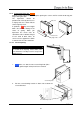
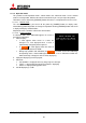
1.3. Connecting
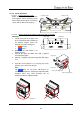
1.3.1. Control signal connection
An external controller such as a personal computer etc. can control cubes through RS-232 format
communication. In the case of a display wall, connect the external controller to a MASTER cube
set by dipswitch (chapter
1.4.2, on page 28) with RS-232 cross cable, and connect CONTROL IN
and CONTROL OUT terminals between cubes with supplied control cables. Do not connect to a
loop.
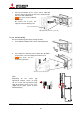
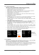
Allocating ID numbers by dipswitch, each cube can be controlled separately by one controller. Up
to 64 cubes can be chained in one control line.
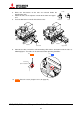
1.3.2. Image signal connection
Connect (an) image input source(s) with cubes adequately.
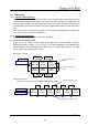
1.3.2.1. In the case of daisy chain
In the case of an enlarged image displaying with digital daisy chain connection, install the
optional input boards (chapter 1.2.3, on page 7) and connect DIGITAL IN and DIGITAL OUT
terminals between cubes with digital cables (DVI-D) that are supplied with the boards. The digital
image signal can be chained up to 16 cubes.
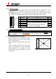
In the case of 3 by 2
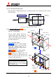
In the case of 6 by 1
(In this case, an image signal cannot be connected to a loop.)
ID 1
MASTER
ID 2
SLAVE
ID 3
SLAVE
ID 4
SLAVE
ID 5
SLAVE
ID 6
SLAVE
ID 1
MASTER
ID 2
SLAVE
ID 3
SLAVE
ID 4
SLAVE
ID 5
SLAVE
ID 6
SLAVE
Video device
External controller
Supplied digital cables
(6 pcs)
Supplied control cables
(5 pcs)
Supplied digital cables (5 pcs)
Supplied control cables (5 pcs)
Video device
External controller