SPLIT-TYPE, HEAT PUMP AIR CONDITIONERS SPLIT-TYPE, AIR CONDITIONERS May 2008 No.OC331 REVISED EDITION-B SERVICE MANUAL Indoor unit [Model names] [Service Ref.] PKA-RP50FAL2 PKA-RP60FAL PKA-RP71FAL PKA-RP100FAL PKA-RP50FAL2 PKA-RP60FAL PKA-RP71FAL PKA-RP100FAL PKA-RP50FAL2#1 PKA-RP60FAL#1 PKA-RP71FAL#1 PKA-RP100FAL#1 PKH-P60FALH PKH-P71FALH PKH-P100FALH PKH-P60FALH PKH-P71FALH PKH-P100FALH Revision: • PKA-RP50~100FAL(2)#1 are added in REVISED EDITION-B. • Some descriptions have been modified.
1 TECHNICAL CHANGES PKA-RP50FAL2 PKA-RP60FAL PKA-RP71FAL PKA-RP100FAL PKA-RP50FAL2#1 PKA-RP60FAL#1 PKA-RP71FAL#1 PKA-RP100FAL#1 INDOOR CONTROLLER BOARD(I.B.) has been changed. 2 REFERENCE MANUAL 2-1. OUTDOOR UNIT’S SERVICE MANUAL Service Ref. Service Manual No. PUHZ-RP35/50/60/71/100/125/140VHA(1) PUHZ-RP100/125/140YHA PUHZ-RP71/100/125/140VHA(1)-A PUHZ-RP200/250YHA(1)(2) PUHZ-RP200/250YHA(1)-A PU(H)-P • VGAA.UK PU(H)-P • YGAA.UK PUHZ-P100/125/140VHA.
SAFETY PRECAUTION 3-1. ALWAYS OBSERVE FOR SAFETY Before obtaining access to terminal, all supply circuits must be disconnected. 3-2. CAUTIONS RELATED TO NEW REFRIGERANT Cautions for units utilizing refrigerant R407C Do not use the existing refrigerant piping. Use liquid refrigerant to seal the system. The old refrigerant and lubricant in the existing piping contains a large amount of chlorine which may cause the lubricant deterioration of the new unit.
[1] Cautions for service ·After recovering the all refrigerant in the unit, proceed to working. ·Do not release refrigerant in the air. ·After completing the repair service, recharge the cycle with the specified amount of liquid refrigerant. [2] Refrigerant recharging (1) Refrigerant recharging process 1Direct charging from the cylinder. ·R407C cylinder are available on the market has a syphon pipe. ·Leave the syphon pipe cylinder standing and recharge it.
CAUTIONS RELATED TO NEW REFRIGERANT Cautions for units utilizing refrigerant R410A Use new refrigerant pipes. Do not use refrigerant other than R410A. In case of using the existing pipes for R22, be careful with the followings. · For PR60/71VHA3 and RP100 be sure to perform replacement operation before test run. · Change flare nut to the one provided with this product. Use a newly flared pipe. · Avoid using thin pipes. If other refrigerant (R22 etc.
Unit Gravimeter [3] Service tools Use the below service tools as exclusive tools for R410A refrigerant. No. 1 Tool name Gauge manifold Specifications ·Only for R410A ·Use the existing fitting specifications. (UNF1/2) ·Use high-tension side pressure of 5.3MPa·G or over. 2 Charge hose 3 Electronic scale 4 Gas leak detector ·Use the detector for R134a, R407C or R410A. 5 Adaptor for reverse flow check ·Attach on vacuum pump.
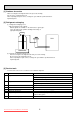
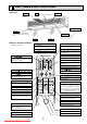
4 PART NAMES AND FUNCTIONS Indoor Unit Air intake Room air is suctioned in here. Filter Air intake grille (Removes dust and dirt from the intake air.) Indicator lamp section Guide vane Air flow can be changed to horizontally by moving the Guide vane to the left or right. Swing louvers Air outlet Wireless remote controller When cover is open. Air outlet Disperses airflow up and down as well as adjusts the angle of air flow direction.
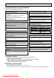
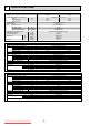
INDOOR UNIT INDOOR UNIT INDOOR UNIT 5 SPECIFICATIONS Service Ref. Mode Power supply(phase, cycle, voltage) Input Running current Starting current External finish Heat exchanger Fan Fan(drive) x No. Fan motor output Airflow(Low-High) External static pressure Operation control & Thermostat Noise level(Low-High) Unit drain pipe O.D. Dimensions W D H Weight Service Ref. Mode Power supply(phase, cycle, voltage) Input Running current Starting current External finish Heat exchanger Fan Fan(drive) x No.
INDOOR UNIT INDOOR UNIT INDOOR UNIT Service Ref. Mode Power supply(phase, cycle,voltage) Input +1 Running current +1 Starting current +1 External finish Heat exchanger Fan Fan(drive) x No. Fan motor output Airflow(Low-High) External static pressure Booster heater +1 Operation control & Thermostat Noise level(Low-High) Unit drain pipe O.D. Dimensions W D H Weight Service Ref.
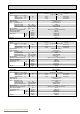
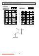
6 NOISE CRITERION CURVES PKA-RP50FAL2 PKA-RP50FAL2#1 PKA-RP60/71FAL PKA-RP60/71FAL#1 PKH-P60/71FALH NOTCH SPL(dB) High 45 Low 39 PKA-RP100FAL PKA-RP100FAL#1 PKH-P100FALH LINE 80 70 NC-70 60 NC-60 50 NC-50 40 NC-40 30 NC-30 20 10 LINE 90 OCTAVE BAND SOUND PRESSURE LEVEL, dB(0dB=0.0002 μbar) OCTAVE BAND SOUND PRESSURE LEVEL, dB(0dB=0.
OUTLINES AND DIMENSIONS 7 PKA-RP50FAL2 PKH-P60FALH PKH-P71FALH Unit : mm PKA-RP50FAL2#1 PKA-RP60FAL PKA-RP60FAL#1 PKA-RP71FAL PKA-RP71FAL#1 Display section 62.5 Top 45 235 235 45 235 45 Defrosting Initial heating lamp 13 235 Power lamp Front Right side 1400 Left side Emergency switch(Heat) Emergency switch(Cool) Receiving section 235 Knockout hole for right piping Refrigerant pipe.
PKH-P100FALH PKA-RP100FAL Unit : mm PKA-RP100FAL#1 Top 62.5 Display section 45 235 45 235 45 235 235 45 13 235 Receiving section Emergency switch(Heat) Emergency switch(Cool) Defrosting Initial heating lamp Power lamp Front Knockout hole for right piping Right side 1680 Left side 235 1370 Air intake 340 197 A Knockout hole for left piping C Terminal block for indoor/outdoor connecting line 15 Terminal block for heater (PKH only) Liquid pipe Gas pipe 25 Drain hose O.D.
WIRING DIAGRAM PKA-RP50FAL2 PKA-RP60FAL PKA-RP50FAL2#1 PKA-RP60FAL#1 PKH-P60FALH PKH-P71FALH SYMBOL P.B I.B FUSE ZNR CN2L CN32 CN41 CN51 SW1 SW2 SWE X4 BCR LED1 LED2 LED3 SYMBOL C MF MV TB2 NAME INDOOR POWER BOARD INDOOR CONTROLLER BOARD FUSE(T6.3AL250V) VARISTOR CONNECTOR(LOSSNAY) CONNECTOR(REMOTE SWITCH) CONNECTOR(HA TERMINAL-A) CONNECTOR(CENTRALLY CONTROL) SWITCH (MODEL SELECTION) +See Table 1. SWITCH (CAPACITY CODE) +See Table 2.
9 REFRIGERANT SYSTEM DIAGRAM PKA-RP50FAL2 PKA-RP60FAL PKA-RP71FAL PKA-RP100FAL PKA-RP50FAL2#1 PKA-RP60FAL#1 PKA-RP71FAL#1 PKA-RP100FAL#1 PKH-P60FALH PKH-P71FALH PKH-P100FALH Strainer #50 Heat exchanger Refrigerant GAS pipe connection (Flare) Condenser/evaporator temperature thermistor (TH5) Refrigerant flow in cooling Refrigerant flow in heating Refrigerant LIQUID pipe connection (Flare) Pipe temperature thermistor/liquid (TH2) Room temperature thermistor (TH1) Distributor with strainer #50 Downlo
10 TROUBLESHOOTING 10-1. TROUBLESHOOTING Present and past error codes are logged and displayed on the wired remote controller or controller board of outdoor unit. Actions to be taken for service and the trouble reoccurrence at field are summarized in the table below. Check the contents below before investigating details.
10-2. MALFUNCTION-DIAGNOSIS METHOD BY REMOTE CONTROLLER When a malfunction occurs to air conditioner, both indoor unit and outdoor unit will stop and operation lamp blinks to inform unusual stop. [Procedure] Refrigerant address display CHECK CHECK display Temperature button TEMP ON/OFF 1. Press the CHECK button twice. • "CHECK" lights, and refrigerant address "00" flashes.
• Refer to the following tables for details on the check codes. [Output pattern A] Beeper sounds OPERATION INDICATOR lamp flash pattern Beep Beep Beep Beep Off Beep 1st 2 nd 3 rd nth On On On On Beep Beep 1st Off On 2 nd · · · Repeated On 0.5 sec. Approx. 2.5 sec. 0.5 sec. 0.5 sec. Self-check Approx. 2.5 sec. 0.5 sec. 0.5 sec. 0.5 sec.
• On wireless remote controller The continuous buzzer sounds from receiving section of indoor unit. Blink of operation lamp • On wired remote controller Check code displayed in the LCD. • If the unit cannot be operated properly after test run, refer to the following table to find the cause.
Note: Refer to the manual of outdoor unit for the details of display such as F, U, and other E. 10-3. SELF-DIAGNOSIS ACTION TABLE Error Code P1 Abnormal point and detection method Cause Countermeasure Room temperature thermistor (TH1) 1 The unit is in 3-minute resume prevention mode if short/open of thermistor is detected. Abnormal if the unit does not reset normally after 3 minutes. (The unit returns to normal operation, if it has been reset normally.
Error Code P6 Abnormal point and detection method Freezing/overheating protection is working 1 Freezing protection (Cooling mode) The unit is in 6-minute resume prevention mode if pipe temperature stays under -15: for 3 minutes, 3 minutes after the compressor started. Abnormal if it stays under -15: for 3 minutes again within 16 minutes after 6-minute resume prevention mode.
Error Code P9 Abnormal point and detection method Pipe temperature thermistor / Condenser-Evaporator (TH5) 1 The unit is in 3-minute resume protection mode if short/open of thermistor is detected. Abnormal if the unit does not get back to normal within 3 minutes. (The unit returns to normal operation, if it has been reset normally.
Error Code Abnornal point and detection method Cause Countermeasure E6 Indoor/outdoor unit communication error (Signal receiving error) 1 Abnormal if indoor controller board cannot receive any signal normally for 6 minutes after turning the power on. 2 Abnormal if indoor controller board cannot receive any signal normally for 3 minutes.
10-4. TROUBLESHOOTING BY INFERIOR PHENOMENA Note: Refer to the manual of outdoor unit for the detail of remote controller. Phenomena (1)LED2 on indoor controller board is off. Cause • When LED1 on indoor controller board is also off. 1 Power supply of rated voltage is not supplied to outdoor unit. 2 Defective outdoor controller circuit board. 3 Power supply of 220~240V is not supplied to indoor unit. 4 Defective indoor power board. 5 Defective indoor controller board.
Note: Refer to the manual of outdoor unit for the detail of remote controller. Phenomena Cause Countermeasure (2)LED2 on indoor controller board is blinking. • When LED1 on indoor controller board is also blinking. Check indoor/outdoor unit connecting wire Connection failure of indoor/outdoor unit connecting for connection failure. wire • When LED1 is lit. 1 Check the connection of remote controller wires in case of twin triple indoor 1 Mis-wiring of remote controller wires unit system.
10-5. EMERGENCY OPERATION 10-5-1. When wireless remote controller troubles or its battery is exhausted 1. Emergency operation is available in such a case using emergency operation switch equipped next to the receiver of indoor unit. 2. To start operation • Cooling Operation·······Press (Cooling) switch. • Heating Operation·······Press (Heating) switch. wWhen the unit starts operating, the power lamp is lit.
10-6. HOW TO CHECK THE PARTS PKH-P60FALH PKA-RP50FAL2 PKA-RP50FAL2#1 PKH-P71FALH PKA-RP60FAL PKA-RP60FAL#1 PKH-P100FALH PKA-RP71FA PKA-RP71FAL#1 Parts name Check points Room temperature thermistor (TH1) Pipe temperature thermistor (TH2) Condenser/evaporator temperature thermistor (TH5) Fan motor Disconnect the connector then measure the resistance with a tester. (Surrounding temperature 10 ~30 ) Red 1 2 White 2 3 Black Abnormal Open or short 3 Protector OFF:130±5 ON :80±20 Red–Black 99.
10-7. TEST POINT DIAGRAM 10-7-1. Indoor controller board PKA-RP50FAL2 PKA-RP50FAL2#1 PKA-RP60FAL PKA-RP60FAL#1 PKA-RP71FAL PKA-RP71FAL#1 PKA-RP100FAL PKA-RP100FAL#1 CN3C Transmission (Indoor/ outdoor) (0~24V DC) CN2D Connect to the indoor power board (CN2S) (12.5~13.7V DC) PKH-P60FALH PKH-P71FALH PKH-P100FALH LED1 Power supply (I.B) LED2 Power supply (R.B) LED3 Transmission (Indoor/ outdoor) CN22 Connect to the terminal block(TB5) (Remote controller connecting wire) (10.4~14.
10-7-2. Indoor power board PKA-RP50FAL2 PKA-RP50FAL2#1 PKA-RP60FAL PKA-RP60FAL#1 PKA-RP71FAL PKA-RP71FAL#1 PKA-RP100FAL PKA-RP100FAL#1 PKH-P60FALH PKH-P71FALH PKH-P100FALH CN2S Connect to the indoor controller board (CN2D) Between 1 to 3 12.6-13.7V DC (Pin1 (+)) CNSK Connect to the indoor controller board (CNDK) Between 1 to 3 220-240V AC Downloaded from AC-Manual.
10-8. FUNCTIONS OF DIP SWITCH AND JUMPER WIRE Each function is controlled by the dip switch and the jumper wire on control p.c. board. SW1 and SW2 are equipped only for service parts. Model setting and capacity setting are memorized in the nonvolatile memory of the control p.c. board of the unit.
11 SPECIAL FUNCTION 11-1. ROTATION FUNCTION(AND BACK-UP FUNCTION, 2ND STAGE CUT-IN FUNCTION) For PKA-RP50FAL2#1,PKA-RP60/71/100FAL#1 11-1-1. Operation (1) Rotation function (and Back-up function) • Outline of functions · Main and sub unit operate alternately according to the interval of rotation setting. w Main and sub unit should be set by refrigerant address.
11-1-2. How to set rotation function(Back-up function, 2nd stage cut-in function) You can set these functions by wired remote controller.(Maintenance monitor) NOTICE Both main and sub unit should be set in same setting. Every time replacing indoor controller board for servicing, the function should be set again. (1) Request Code List Rotation setting Setting No. (Request code) No.1 (310) No.2 (311) No.3 (312) No.4 (313) No.5 (314) No.6 (315) No.7 (316) No.8 (317) No.
(2) Setting method of each function by wired remote controller B: Refrigerant address C: Data display area D: Request code display area 1. Stop operation( ). 2. Press the TEST button ( ) for 3 seconds so that [Maintenance mode] appears on the screen ( ). After a while, [00] appears in the refrigerant address number display area.(at ) 3. Press the CHECK button ( ) for 3 seconds to switch to [Maintenance monitor].
12 DISASSEMBLY PROCEDURE PKA-RP50FAL2 PKA-RP60FAL PKA-RP60FAL#1 PKH-P60FALH PKA-RP50FAL2#1 PKA-RP71FAL PKA-RP71FAL#1 PKH-P71FALH PKA-RP100FAL PKA-RP100FAL#1 PKH-P100FALH OPERATING PROCEDURE PHOTOS&ILLUSTRATION 1. Removing the lower side of the indoor unit from the installation plate (1) Remove the 2 screws. Hang the indoor unit hangers to the catches on the installation plate. Figure 1 Hanger of indoor unit Catch of installation plate Metal fixture Screws 2.
OPERATING PROCEDURE PHOTOS&ILLUSTRATION (9) Remove the screws of the indoor controller board case, and pull out the indoor controller board case. Then the indoor power board, the fan motor capacitor and the heater relay can be serviced. Photo 3 Relay Indoor power board Capacitor Indoor controller board case 5. Removing the vane motor (1) Remove the right side panel. (2) Remove the screw of the electrical parts box cover, and remove the cover.
OPERATING PROCEDURE PHOTOS 8. Removing the line flow fan and the fan motor (1) Remove the left and right side panels. (2) Remove the grilles. (3) Remove the electrical parts box. (4) Remove the drain pan. (5) Loosen the screw that fixes the line flow fan to the fan motor. (See Photo 7. ) (6) Remove the 4 screws of the motor fixture, and remove the fan motor and the motor fixture at a time (See Photo 8.
13 PARTS LIST(non-RoHS compliant) ELECTRICAL PARTS PKA-RP60FAL PKH-P60FALH PKA-RP71FAL PKH-P71FALH 41 40 36 39 38 1 37 34 2 35 33 3 36 4 32 31 5 28 30 6 29 7 27 26 9 10 19 22 23 18 25 24 11 13 12 14 Q'ty/set No. 1 2 3 Part No.
From the previous page. Part number that is circled is not shown in the figure. , Q ty/set No. Part No. Part Name 17 R01 E02 239 FUSE 18 — 19 — Specification 250V 6.3A PKH-P PKA-RP 60 60 71 FALH FALH FAL 1 1 1 71 FAL 1 Remarks (Drawing No.) FUSE CONTROLLER COVER 1 1 1 1 (BG02A648G03) CONTROLLER CASE 1 1 1 1 (BG25J080H02) 1 1 1 1 20 R01 E02 313 INDOOR POWER BOARD Wiring RecomDiagram mended , Q ty Symbol P.
ELECTRICAL PARTS PKA-RP100FAL PKH-P100FALH 41 36 40 39 38 1 37 34 2 35 33 3 36 4 32 31 5 28 30 6 29 7 27 20 21 8 26 19 22 23 18 25 24 9 11 10 13 12 14 Q'ty/set No. Part No. 1 R01 Z61 102 BEARING MOUNT R01 16G 114 LEFT LINEFLOW FAN 1 R01 17G 114 LEFT LINEFLOW FAN T7W E22 480 HEAT EXCHANGER T7W E58 480 HEAT EXCHANGER 2 3 Part Name Specification PKH - P PKA - RP 100FALH 100FAL 1 1 15 16 17 Wiring RecomRemarks Diagram mended (Drawing No.
From the previous page. Part number that is circled is not shown in the figure. , Q ty/set No. Part No. Part Name 17 R01 E02 239 FUSE — 18 CONTROLLER COVER 19 Specification 250V 6.3A — CONTROLLER CASE R01 E02 313 20 INDOOR POWER BOARD R01 71G 215 21 HEATER CONTACTOR 22 T7W E23 716 TERMINAL BLOCK 23 T7W A14 716 TERMINAL BLOCK 31 32 33 — PN4S70-K 1 (BG02A648G03) 1 1 (BG25J080H02) 1 1 Wiring Diagram Symbol FUSE P.
STRUCTURAL PARTS PKA-RP60FAL PKH-P60FALH PKA-RP71FAL PKH-P71FALH 12 11 13 1 10 9 8 2 3 5 7 4 6 Part number that is circled is not shown in the figure. , Q ty/set No. Part No.
STRUCTURAL PARTS PKA-RP100FAL PKH-P100FALH 12 11 13 1 14 10 9 8 2 3 7 5 4 6 Part number that is circled is not shown in the figure. , Q ty/set No. Part No. Part Name Specification PKA- PKH- Remarks (Drawing No.
14 RoHS PARTS LIST ELECTRICAL PARTS PKA-RP50FAL2 PKA-RP50FAL2#1 PKH-P60FALH PKA-RP60FAL PKA-RP60FAL#1 PKH-P71FALH 41 PKA-RP71FAL PKA-RP71FAL#1 36 40 39 38 1 37 34 2 35 33 3 36 4 32 31 5 28 30 6 29 7 26 9 13 12 14 15 16 17 Q'ty/set PKA-RP RoHS Wiring recomRemarks Diagram mended (Drawing No.
From the previous page. Part number that is circled is not shown in the figure. No. RoHS , Q ty/set Part No. Part Name 17 G R01 E06 239 FUSE Specification 250V 6.3A Remarks PKA-RP (Drawing No.) 50FAL2 60FAL 71FAL 60FALH 71FALH 50FAL2#1 60FAL#1 71FAL#1 1 1 1 1 1 PKH-P 18 G — CONTROLLER COVER 1 1 1 1 1 (BG02A648G03) 19 G — CONTROLLER CASE 1 1 1 1 1 (BG25J080H02) 1 1 1 1 1 20 G R01 E38 313 INDOOR POWER BOARD Wiring RecomDiagram mended , Q ty Symbol FUSE P.
ELECTRICAL PARTS PKA-RP100FAL PKA-RP100FAL#1 41 PKH-P100FALH 36 40 39 38 1 37 34 2 35 33 3 36 4 32 31 5 28 30 6 29 7 27 20 21 8 26 19 22 23 18 25 24 9 11 10 13 12 14 RoHS Part No. 100FALH 100FAL 100FAL#1 1 G R01 Z61 102 BEARING MOUNT 1 1 1 G R01 19G 114 LEFT LINEFLOW FAN 1 G R01 E24 114 LEFT LINEFLOW FAN 1 1 G T7W H35 480 HEART EXCHANGER G T7W H38 480 HEART EXCHANGER G T7W E25 529 DRAIN PAN 3 4 16 17 Q'ty/set No.
From the previous page. Part number that is circled is not shown in the figure. No. RoHS Q'ty/set Part No. Part Name FUSE Specification PKH-P 100FALH 100FAL 100FAL#1 1 1 1 Remarks (Drawing No.) Wiring Diagram Symbol 17 G R01 E06 239 18 G — CONTROLLER COVER 1 1 1 (BG02A648G03) 19 G — CONTROLLER CASE 1 1 1 (BG25J080H02) 20 G R01 E38 313 INDOOR POWER BOARD 1 1 1 P.
STRUCTURAL PARTS PKA-RP50FAL2 PKA-RP50FAL2#1 PKH-P60FALH PKA-RP60FAL PKA-RP60FAL#1 PKH-P71FALH 12 PKA-RP71FAL PKA-RP71FAL#1 11 13 1 10 9 8 2 3 5 7 4 6 Part number that is circled is not shown in the figure. No. RoHS Q'ty/set Part No. Part Name Specifications Wiring RecomRemarks Diagram mended 50FAL2 50FAL2#1 60FALH (Drawing No.
STRUCTURAL PARTS PKA-RP100FAL PKA-RP100FAL#1 13 PKH-P100FALH 11 12 1 14 10 9 8 2 3 7 5 4 6 Part number that is circled is not shown in the figure. Q'ty/set PKA-RP Wiring RecomRemarks Diagram mended (Drawing No.) Symbol Q'ty 100FAL 100FAL#1 100FALH RoHS PKH-P No. Part No.
TM HEAD OFFICE : TOKYO BLDG., 2-7-3, MARUNOUCHI, CHIYODA-KU, TOKYO 100-8310, JAPAN CCopyright 2005 MITSUBISHI ELECTRIC ENGINEERING CO., LTD. Distributed in May 2008 No.OC331 REVISED EDITION-B PDF 7 Distributed in Jun. 2006 No.OC331 REVISED EDITION-A PDF 8 Distributed in May 2005 No.OC331 PDF 9 Made in Japan. Downloaded from AC-Manual.com Manuals New publication, effective May 2008. Specifications subject to change without notice.