SPLIT-TYPE, HEAT PUMP AIR CONDITIONERS SPLIT-TYPE, AIR CONDITIONERS May 2011 No. OCH452 REVISED EDITION-A SERVICE MANUAL Indoor unit [Model names] PKA-RP60KAL PKA-RP71KAL PKA-RP100KAL [Service Ref.] PKA-RP60KAL.TH PKA-RP71KAL.TH PKA-RP100KAL.TH Revision: • 6. OUTLINES AND DIMENSIONS has been modified in REVISED EDITION-A. • Some descriptions have been modified. • Please void OCH452. NOTE: • This manual describes only service data of the indoor units.
1 REFERENCE MANUAL OUTDOOR UNIT’S SERVICE MANUAL Service Manual No. Service Ref. PUHZ-RP35/50/60/71VHA4 PUHZ-RP100/125/140VKA PUHZ-RP100/125/140/200/250YKA OCH451 OCB451 PU(H)-P71/100VHA#2.UK PU(H)-P71/100/125/140YHA#2.UK OC379 PUHZ-P100/125/140VHA3.
2 SAFETY PRECAUTION 2-1. ALWAYS OBSERVE FOR SAFETY Before obtaining access to terminal, all supply circuits must be disconnected. 2-2. CAUTIONS RELATED TO NEW REFRIGERANT Cautions for units utilising refrigerant R410A Use new refrigerant pipes. Do not use refrigerant other than R410A. In case of using the existing pipes for R22, be careful with the followings. · For RP100, 125 and 140, be sure to perform replacement operation before test run. · Change flare nut to the one provided with this product.
[1] Cautions for service (1) Perform service after recovering the refrigerant left in unit completely. (2) Do not release refrigerant in the air. (3) After completing service, charge the cycle with specified amount of refrigerant. (4) When performing service, install a filter drier simultaneously. Be sure to use a filter drier for new refrigerant. [2] Additional refrigerant charge When charging directly from cylinder · Check that cylinder for R410A on the market is syphon type.
Wireless remote controller CHECK TEST RUN display CHECK and TEST RUN display indicate that the unit is being checked or test-run. display Lights up while the signal is transmitted to the indoor unit when the button is pressed. MODEL SELECT display Blinks when model is selected. display SET TEMP. display indicates the desired temperature which is set. CLOCK display display Displays the current time. OPERATION MODE display Operation mode display indicates which operation mode is in effect.
INDOOR UNIT INDOOR UNIT INDOOR UNIT 4 SPECIFICATIONS Service Ref. Mode Power supply (phase, cycle, voltage) Input Running current External finish (Panel) Heat exchanger Fan Fan (drive) % No. Fan motor output Airflow (Low-Middle-High) External static pressure Booster heater Operation control & Thermostat Noise level (Low-Middle-High) Field drain pipe I.D. Dimensions W D H Weight Service Ref.
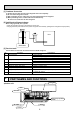
5 NOISE CRITERION CURVES 5-1. SOUND LEVELS Sound level at anechoic room : Low-Middle-High Sound level dB (A) 39 - 42 - 45 41 - 45 - 49 1.0m PKA-RP60,71KAL,TH PKA-RP100KAL,TH Measurement location 1.0m * Measured in anechoic room. 5-2. NOISE CRITERION CURVES PKA-RP60,71KAL External static pressure : 0Pa Power source : 220, 230, 240V, 50Hz 70.0 High Low 65.0 Octave band pressure level (dB) 0dB=20μPa Octave band pressure level (dB) 0dB=20μPa 70.
6 OUTLINES AND DIMENSIONS PKA-RP60KAL.TH PKA-RP71KAL.TH PKA-RP100KAL.TH Unit : mm Top side 431.7 11 140.3 65.2 423.
7 WIRING DIAGRAM PKA-RP60KAL.TH PKA-RP71KAL.TH PKA-RP100KAL.TH [LEGEND] SYMBOL I.B CN2L CN32 CN41 CN51 CN90 DSA FUSE LED1 LED2 LED3 SW1 SW2 SWE X1 ZNR01,02 CNP CN4F R.B TB6 NAME Indoor controller board Connector (LOSSNAY) Connector (Remote switch) Connector (HA terminal-A) Connector (Centrally control) Connector (Remote operation adapter) Surge absorber FUSE (T3.15AL250V) Power supply (I.B) Power supply (R.
8 REFRIGERANT SYSTEM DIAGRAM PKA-RP60KAL.TH PKA-RP71KAL.TH PKA-RP100KAL.TH Strainer (#50) Heat exchanger Refrigerant GAS pipe connection (Flare) Thermistor TH2 Pipe temperature(Liquid) Thermistor TH5 (Cond./ Eva.
9 TROUBLESHOOTING 9-1. TROUBLESHOOTING Present and past error codes are logged and displayed on the wired remote controller or controller board of outdoor unit. Actions to be taken for service and the trouble reoccurrence at field are summarized in the table below. Check the contents below before investigating details.
9-2. MALFUNCTION-DIAGNOSIS METHOD BY REMOTE CONTROLLER When a malfunction occurs to air conditioner, both indoor unit and outdoor unit will stop and operation lamp blinks to inform unusual stop. [Procedure] Refrigerant address display CHECK CHECK display Temperature button TEMP ON/OFF 1. Press the CHECK button twice. • "CHECK" lights, and refrigerant address "00" flashes.
• Refer to the following tables for details on the check codes. [Output pattern A] Beeper sounds OPERATION INDICATOR lamp flash pattern Beep Beep Beep Beep Off Beep 1st 2 nd 3 rd nth On On On On Beep Beep 1st Off On 2 nd · · · Repeated On 0.5 sec. Approx. 2.5 sec. 0.5 sec. 0.5 sec. Self-check Approx. 2.5 sec. 0.5 sec. 0.5 sec. 0.5 sec.
• On wireless remote controller The continuous buzzer sounds from receiving section of indoor unit. Blink of operation lamp • On wired remote controller Check code displayed in the LCD. • If the unit cannot be operated properly after test run, refer to the following table to find the cause.
Note: Refer to the manual of outdoor unit for the details of display such as F, U, and other E. 9-3. SELF-DIAGNOSIS ACTION TABLE Error Code P1 Abnormal point and detection method Room temperature thermistor (TH1) 1 The unit is in 3-minute resume prevention mode if short/open of thermistor is detected. Abnormal if the unit does not reset normally after 3 minutes. (The unit returns to normal operation, if it has been reset normally.) 2 Constantly detected during cooling, drying, and heating operation.
Error Code Abnormal point and detection method Freezing/overheating protection is operating 1 Freezing protection (Cooling mode) The unit is in 6-minute resume prevention mode if pipe temperature stays under -15: for 3 minutes, 3 minutes after the compressor started. Abnormal if it stays under -15: for 3 minutes again within 16 minutes after 6-minute resume prevention mode.
Error Code P9 Abnormal point and detection method Pipe temperature thermistor / Condenser-Evaporator (TH5) 1 The unit is in 3-minute resume protection mode if short/open of thermistor is detected. Abnormal if the unit does not get back to normal within 3 minutes. (The unit returns to normal operation, if it has been reset normally.
Error Code E6 E7 Fb E1 or E2 PA Abnormal point and detection method Indoor/outdoor unit communication error (Signal receiving error) 1 Abnormal if indoor controller board cannot receive any signal normally for 6 minutes after turning the power on. 2 Abnormal if indoor controller board cannot receive any signal normally for 3 minutes.
9-4. TROUBLESHOOTING BY INFERIOR PHENOMENA Note: Refer to the manual of outdoor unit for the detail of remote controller. Phenomena (1) LED2 on indoor controller board is off. Cause • When LED1 on indoor controller board is also off. 1 Power supply of rated voltage is not supplied to outdoor unit. 2 Defective outdoor controller circuit board 3 Power supply of 220~240V is not supplied to indoor unit.
Note: Refer to the manual of outdoor unit for the detail of remote controller. Phenomena (2) LED2 on indoor controller board is blinking. Cause Countermeasure • When LED1 on indoor controller board is also blinking. Check indoor/outdoor unit connecting wire Connection failure of indoor/outdoor unit connecting for connection failure. wire • When LED1 is lit.
9-5. EMERGENCY OPERATION 9-5-1. When wireless remote controller troubles or its battery is exhausted When the remote controller cannot be used When the batteries of the remote controller run out or the remote controller malfunctions, the emergency operation can be done using the emergency buttons. DEFROST/STAND BY lamp (ORANGE) Operation lamp (GREEN) Emergency operation switch (cooling/heating) Receiver • Each press of the emergency operation switch will toggle the operation mode.
9-6. HOW TO CHECK THE PARTS PKA-RP60KAL.TH PKA-RP71KAL.TH Parts name Check points Disconnect the connector then measure the resistance using a tester. (At the ambient temperature 10 ~30 ) Room temperature thermistor (TH1) Liquid pipe temperature thermistor (TH2) Condenser / Evaporator temperature thermistor (TH5) Vane motor (MV) Red Normal Abnormal 4.3k ~9.6k Open or short Refer to the thermistor. Measure the resistance between the terminals using a tester.
9-6-2. DC Fan motor (fan motor/indoor controller circuit board) Check method of DC fan motor (fan motor/indoor controller circuit board) Notes · High voltage is applied to the connecter (CNMF) for the fan motor. Pay attention to the service. · Do not pull out the connector (CNMF) for the motor with the power supply on. (It causes trouble of the indoor controller circuit board and fan motor.) Self check Symptom : The indoor fan cannot turn around.
9-7. TEST POINT DIAGRAM PKA-RP60KAL.TH PKA-RP71KAL.TH PKA-RP100KAL.TH CNMF Connect to the fan motor (MF) 1-3 : DC310~340V 4-3 : DC15V 5-3 : DC0~6.5V 6-3 : DC0 or DC15V CN01 Connect to the Terminal block (TB4) 1-3 : 220-240VAC SWE Emergency operation connector FUSE (3.15A 250V) CNP Drain pump output (220-240VAC) (option) { SW1 Model selection LED1:Power supply (I.B) LED2:Power supply (R.
9-8. FUNCTIONS OF DIP SWITCH AND JUMPER WIRE Each function is controlled by the dip switch and the jumper wire on control P.C. board.
10 SPECIAL FUNCTION 10-1. ROTATION FUNCTION (AND BACK-UP FUNCTION, 2ND STAGE CUT-IN FUNCTION) Optional wired remote controller with terminal bed (PAR-21MAAT-E) are necessary for PKA type. 10-1-1. Operation (1) Rotation function (and Back-up function) • Outline of functions · Main and sub unit operate alternately according to the interval of rotation setting. w Main and sub unit should be set by refrigerant address.
• System constraint · This function is available only in cooling mode. Ex.) Set temp. by R/C = 20: Set point = 26: When request code number is “323”. 26: 2nd unit Cut-in [2nd stage cut-in function]··· Request code number "322~324" Start operation Main unit IC-1 Room temp. Set point Sub unit start operation Room temp. < Set point -4 Sub unit stop Run 4 degree C 22: 2nd unit Cut-out Sub unit IC-2 Stop Run 20: 10-1-2.
(2) Setting method of each function by wired remote controller B: Refrigerant address C: Data display area D: Request code display area 1. Stop operation( ). 2. Press the TEST button ( ) for 3 seconds so that [Maintenance mode] appears on the screen ( ). After a while, [00] appears in the refrigerant address number display area.(at ) 3. Press the CHECK button ( ) for 3 seconds to switch to [Maintenance monitor].
11 DISASSEMBLY PROCEDURE PKA-RP60KAL.TH PKA-RP71KAL.TH PKA-RP100KAL.TH Be careful when removing heavy parts. OPERATION PROCEDURE PHOTOS & ILLUSTRATIONS 1. REMOVING THE PANEL Photo 1 (1) Press and unlock the knobs on both sides of the front grille and lift the front grille until it is level. Pull the hinges forward to remove the front grille. (See Photo 1) (2) Remove 3 screw caps of the panel. Remove 5 screws. (See Photo 1) (3) Unfix 3 hooks.
OPERATION PROCEDURE PHOTOS 3. REMOVING THE ELECTRICAL BOX Photo 4 Connector for ground wire (1) Remove the panel and the corner box. (Refer to 1.) (2) Remove the front and side electrical box covers (each 1 screw). (3) Remove the indoor / outdoor connecting wire from terminal block (TB4). (4) Disconnect the connectors on the indoor controller board. (5) Disconnect the connector for ground wire. (6) Remove the screw on lower side of the electrical box.
OPERATION PROCEDURE PHOTOS 6. REMOVING THE INDOOR FAN MOTOR AND THE LINE FLOW FAN Photo 7 Screw of the motor band (1) Remove the panel and the corner box. (Refer to 1.) (2) Remove the electrical box (Refer to 2.) and the nozzle assembly (Refer to 3.). (3) Remove the water cut. (See Photo 2) (4) Remove the screw fixing the line flow fan. (See Photo 8) (5) Remove 5 screws fixing the motor bed. (See Photo 7) (6) Remove the lead wire of pipe thermistor from the hook of motor bed.
OPERATION PROCEDURE 8. REMOVING THE HEAT EXCHANGER PHOTOS Photo 11 (1) Remove the panel and the corner box. (Refer to 1.) (2) Remove the electrical box (Refer to 3.) and the nozzle assembly (Refer to 4.). (3) Remove the water cut. (4) Remove the pipe thermistors from each holder. (5) Disconnect the connector for ground wire. (6) Remove 3 screws fixing the left side of the heat exchanger. (See Photo 9) (7) Remove the heat exchanger.