
Installation manual

[ IX Troubleshooting ]
- 347 -
HWE09130 GB
I
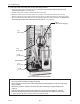
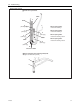
(ø25.4[1”])
2 3
J
(ø15.88[5/8”])
2 3
L
(ø15.88[5/8”])
2 3
K
(ø19.05[3/4”])
2 3
M
(ø19.05[3/4”])
2 3
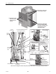
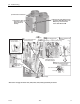
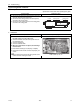
(2) Check valve (CV4a, CV6a, CV8a, CV9a) replacement procedures
Remove the solenoid valve block ASSY following "(1) Solenoid valve block ASSY (SV4a, SV4b, SV4c, SV4d)
replacement procedures" on the front page.
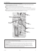
Debraze I-M parts (total 5 places), and remove the Check valve ASSY.
Replace the Check valve (CV4a, CV6a, CV8a, CV9a) to be serviced while it is removed from the unit.
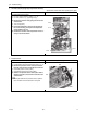
Braze the pipes as they were according to the angle of the pipes on the figure on the next page (Figure as viewed from
point N).
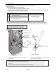
Mount the solenoid valve block ASSY, coil cover, and peripheral cables back in place according to "(1) Solenoid valve
block ASSY (SV4a, SV4b, SV4c, SV4d) replacement procedures" on the front page.
* Precautions for replacing Check valve
• Be sure to perform no-oxidation brazing when brazing.
• Place a wet towel on the check valve when heating pipes to keep the temperature of the valve from exceed-
ing 120°C [248°F].
• After brazing, check the condition around the brazing. After confirming no leakage, evacuate the air
inside. (*1)
• Perform carefully with the flame direction so that it does not burn cables and plates etc. in the unit.
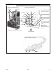
• Remove the brazing part protecting heat exchanger fins not to be burn, and replace the service parts.
*1: Refer to Chapter I [8] Vacuum Drying (Evacuation) for detailed procedure.
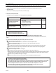
Part A
(Refer to the next page.)
* After removing Solenoid valve block ASSY
2
1
3
4