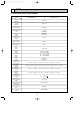
Outdoor unit RP8 RP10 permitted pipe length 80m or less At time of shipping (kg) 10.5 A+B+C+D 30 m and less No additional charge necessary 10.5 Amount of additional refrigerant charge (kg) 31-40 m and less 41-50 m and less 51-60 m and less 61-70 m and less 71-80 m and less The additional charge 0.9 kg 1.8 kg 2.7 kg 3.6 kg 1.2 kg 2.4 kg 3.6 kg 4.8 kg amount is obtained by the following formula.OC317-1.qxp 04.11.26 9:33 AM Page 24 Refrigerant collecting (pump down) Perform the following procedures to collect the refrigerant when moving the indoor unit or the outdoor unit. 1 Before collecting the refrigerant, first make sure that the all of the SW5 DIP switches for function changes on the control board of the outdoor unit are set to OFF. If all of the SW5 switches are not set to OFF, record the settings and then set all of the switches to OFF. Start collecting the refrigerant.
OC317-1.qxp 04.11.26 9:33 AM 13 Page 25 TROUBLESHOOTING 13-1. TROUBLESHOOTING Present and past error codes are logged and displayed on the wired remote controller and control board of outdoor unit. Actions to be taken for service, which depends on whether or not the inferior phenomenon is reoccurring at service, are summarized in the table below. Check the contents below before investigating details.
OC317-1.qxp 04.11.26 9:33 AM Page 26 13-2. CHECK POINT UNDER TEST RUN (MA remote controller) (1) Before test run • After installation of indoor and outdoor units, piping work and electric wiring work, re-check that there is no refrigerant leakage, loosened connections and incorrect polarity. • Measure impedance between the ground and the power supply terminal block(L, N) on the outdoor unit by 500V Merger and check that it is 1.0M" or over.
OC317-1.qxp 04.11.26 9:33 AM Page 27 wPress the remote controller’s CHECK button twice to perform self-diagnosis. See the table below for the contents of LCD display. LCD P1 P2 P4 P5 P6 P8 P9 Contents of inferior phenomena Abnormality of room temperature thermistor Abnormality of pipe temperature thermistor/Liquid Abnormality of drain sensor Drain overflow protection is working. Freezing/overheating protection is working. Abnormality of pipe temperature Abnormality of pipe temperature thermistor/Cond.
OC317-1.qxp 04.11.26 9:33 AM Page 28 13-3. MALFUNCTION-DIAGNOSIS METHOD BY REMOTE CONTROLLER 13-3-1. Error history of unit (1) Wired remote controller Setting number Refrigerant address Unit number Mode number 1Hr. CENTRALLY CONTROLLED ON OFF ˚C CLOCK CHECK ˚C STAND BY DEFROST ERROR CODE NOT AVAILABLE TEMP.
OC317-1.qxp 04.11.26 9:33 AM Page 29 4 To cancel self-diagnosis There are following two methods to cancel self-diagnosis: Press the H “CHECK” button twice within three seconds. ➜Self-diagnosis is cancelled and the display screen will return to the status before self-diagnosis. Press the I “ON/OFF” button. ➜Self-diagnosis is cancelled and indoor unit will stop. This operation is ineffectual when the operation of remote controller is prohibited.
OC317-1.qxp 04.11.26 9:33 AM Page 30 (2) Digital wireless remote controller When a malfunction occurs to air conditioner, both indoor unit and outdoor unit will stop and operation lamp blinks to inform unusual stop. [Procedure] 1. Press the CHECK button twice. • "CHECK" lights, and refrigerant address "00" flashes. • Check that the remote controller's display has stopped before continuing. 2.
OC317-2.qxp 04.11.26 9:39 AM Page 31 13-3-2. Wired Remote controller Diagnosis If operation can not be carried out from remote controller, try remote controller diagnosis with following process. 1 First, check the electricity current marker. When correct voltage (DC12V) is not supplied to remote controller, the electricity current marker is put out. If the electricity current marker is not lighted, check the remote controller wiring and the indoor units.
OC317-2.qxp 04.11.26 9:39 AM Page 32 13-4. SELF-DIAGNOSIS ACTION TABLE Error Code Meaning of error code and detection method (Note 1) Refer to indoor unit section for code P and code E. Case Judgment and action 1 No voltage is supplied to terminal 1 Check following items. a) Power supply breaker block(TB1) of outdoor unit. b) Connection of power supply terminal block. a) Power supply breaker is put (TB1) off.
OC317-2.qxp 04.11.26 9:39 AM Page 33 Error Code Meaning of error code and detection method Indoor/outdoor unit connector mis-wiring, excessive number of units (4 units or more) 1. Outdoor controller circuit board can automatically check the number of connected indoor units. Abnormal if the number cannot be checked automatically due to mis-wiring of indoor/outdoor unit connecting wire and etc. after power is turned on for 4 minutes. EA 2.
OC317-2.qxp 04.11.26 9:39 AM Page 34 Error Code Meaning of error code and detection method Abnormal high pressure (High-pressure switch 63H worked) Abnormal if high-pressure switch 63H worked ( 3.6MPa ) during compressor operation. 63H: High-pressure switch U1 (1302) Abnormal high discharging temperature (1) Abnormal if discharge temperature thermistor (TH4) exceeds 125: or 110: continuously for 5 minutes.
OC317-2.qxp 04.11.26 9:39 AM Page 35 Case Error Code Meaning of error code and detection method Open/short circuit of discharge 1 Disconnection or contact temperature thermistor (TH4) failure of connector (TH4) on the outdoor controller circuit Abnormal if open (3: or less) or short board. (217: or more) is detected during U3 compressor operation. 2 Defective thermistor. (5104) (Detection is inoperative for 10 minutes of 3 Defective outdoor controller compressor starting process and for 10 circuit board.
OC317-2.qxp 04.11.26 9:39 AM Page 36 Error Code Meaning of error code and detection method Case 1 Decrease of power supply voltage. 2 Defective 52C drive circuit of outdoor power circuit board. 3 Disconnection or loose Abnormal if any of followings are detected connection of CN5 on the during compressor operation; outdoor power circuit board or • Instantaneous decrease of DC bus voltage outdoor noise filter circuit to 400V. board. • Increase of DC bus voltage to 760V.
OC317-2.qxp 04.11.26 9:39 AM Page 37 Case Error Code Meaning of error code and detection method Remote controller communication error 1 Defective communication circuit of remote controller. (Signal receiving error) (1) Abnormal if any signal from IC of refrig- 2 Defective communication circuit of indoor controller circuit erant address “0” could not be normally board of refrigerant address received for three minutes. “0”.
OC317-2.qxp 04.11.26 9:39 AM Page 38 Error Code Meaning of error code and detection method P8 Abnormality of pipe temperature 1 Slight temperature difference between indoor room Detected as abnormal when the pipe temtemperature and pipe utes later of compressor start and 6 mintemperature thermistor. utes later of the liquid or condenser/evapo• Shortage of refrigerant rator pipe is out of cooling range.
OC317-2.qxp 04.11.26 9:39 AM Page 39 Error Code Meaning of error code and detection method A6 (6606) Case Judgment and action Communication error with communication processor Defective communication between unit processor and transmission processor Note) The address and attribute display at remote controller indicate the controller that detected abnormality. 1 Data of transmission processor or unit processor is not transmitted normally because of accidental trouble such as noise or thunder surge.
OC317-2.qxp 04.11.26 9:39 AM Page 40 From the previous page. Error Code Meaning of error code and detection method Case Judgment and action 4. If displayed address or attribute is remote controller, Indoor unit detects abnormality when indoor unit transmitted to remote controller and there was no reply (ACK).
OC317-2.qxp 04.11.26 9:39 AM Page 41 Error Code Meaning of error code and detection method M-NET•NO RESPONSE Abnormal if a massage was transmitted and there were reply (ACK) that massage was received, but response command does not return. Transmitting side detects abnormality every 30 seconds, six times continuously. Note) The address and attribute displayed at remote controller is indicate the controller that did not reply (ACK).
OC317-2.qxp 04.11.26 9:39 AM Page 42 Phenomena 5. When operating by the wireless remote controller, beep sound is heard, however, unit does not start operating. 6. Remote controller display works normally and the unit performs cooling operation, however, the capacity cannot be fully obtained. (The air does not cool well.) Factor Countermeasure 1No operation for 2 minutes at most after the power 1Normal operation. supply ON. 2Hand-held remote controller operation is prohibited. 2Normal operation.
OC317-2.qxp 04.11.26 9:39 AM Page 43 13-6. HOW TO CHECK THE PARTS PUHZ-RP8YHA PUHZ-RP10YHA Check points Parts name Thermistor (TH3, TH32) Disconnect the connector then measure the resistance using a tester. (Surrounding temperature 10:~30:) Normal Thermistor (TH4) TH4 Thermistor (TH6) Thermistor (TH7) Abnormal 160k"~410k" TH3, TH32 TH6 4.3k"~9.
OC317-2.qxp 04.11.26 9:39 AM Page 44 13-7. HOW TO CHECK THE COMPONENTS 50 Low temperature thermistors • Thermistor (TH3, TH32) • Thermistor (TH6) • Thermistor (TH7) Resistance (K") 40 Thermistor R0 = 15k' ± 3% B constant = 3480K ± 2% 1 1 Rt =15exp{3480( 273+t – 273 )} 30: 4.3k' 0: 15k' 10: 9.6k' 40: 3.0k' 20: 6.3k' 25: 5.
04.11.26 9:39 AM Page 45 Linear expansion valve (1) Operation summary of the linear expansion valve. • Linear expansion valve open/close through stepping motor after receiving the pulse signal from the outdoor controller circuit board. • Valve position can be changed in proportion to the number of pulse signal.
OC317-2.qxp 04.11.26 9:39 AM Page 46 (3) How to attach and detach the coil of linear expansion valve Linear expansion valve is separable into the main body and the coil as shown in the diagram below. Main body Coil Lead wire Stopper Hold the lower part of the main body (shown as A) firmly so that the main body does not move and detach the coil by pulling it upward. Be sure to detach the coil holding main body firmly. Otherwise pipes can bend due to pressure.
OC317-2.qxp 04.11.26 9:39 AM Page 47 13-8. EMERGENCY OPERATION (1) When the error codes shown below are displayed on outdoor unit or microcomputer for wired remote controller or indoor unit has a failure, but no other problems are found, emergency operation will be available by setting the emergency operation switch (SWE) to ON and short-circuiting the connector (CN31) on outdoor controller circuit board. ●When following abnormalities occur, emergency operation will be available.
OC317-2.qxp 04.11.26 9:39 AM Page 48 13-9.
OC317-2.qxp 04.11.26 9:39 AM Page 49 Outdoor Power circuit board PUHZ-RP8YHA PUHZ-RP10YHA Brief Check of POWER MODULE W Usually, they are in a state of being short-circuited if they are broken. Measure the resistance in the following points (connectors, etc.). If they are short-circuited, it means that they are broken. 1. Check of POWER MODULE 1.Check of DIODE circuit L1 - P1 , L2 - P1 , L3 - P1 , L1 - N1 , L2 - N1 , L3 - N1 2.
OC317-2.qxp 04.11.
OC317-2.qxp 04.11.
OC317-2.qxp 04.11.26 9:39 AM Page 52 13-10. FUNCTION OF SWITCHES, CONNECTORS AND JUMPERS (1) Function of switches Type of Switch No. switch Action by the switch operation Function 1 Compulsory defrosting 2 Abnormal history clear 3 Dip switch SW1 OFF Start Normal When compressor is working in heating operation.
OC317-2.qxp 04.11.26 9:39 AM Page 53 (2) Function of connectors Types Connector Function Connector CN31 Emergency operation Action by the switch operation Short Open Start Normal Effective timing When power supply ON SW6-1 SW6-2 SW6 SW6-3 SW6-4 SW6-5 W1 Model select SW6-6 SW8 SW10 W1 SW8-1 SW10-1 SW10-2 W 1 As for SW8, see also 13-10 (1) Function of switches, as SW8 sets the replacement operation as well.
OC317-2.qxp 04.11.26 9:39 AM Page 54 Special function (a) Low-level sound priority mode (Local wiring) Unit enters into Low-level sound priority mode by SW7-1, 2 and external signal input setting. Inputting external signals to the outdoor unit decreases the outdoor unit operation sound 3 to 4 dB lower than that of usual.
OC317-2.qxp 04.11.26 9:39 AM Page 55 The blinking patterns of both LED1(green) and LED2(red) indicate the types of abnormality when it occurs. Types of abnormality can be indicated in details by connecting an optional part ‘A-Control Service Tool (PAC-SK52ST)’ to connector CNM on outdoor controller circuit board.
OC317-2.qxp 04.11.26 9:39 AM Indication Outdoor controller circuit board LED1 (Green) LED2 (Red) Page 56 Error Error code w1 Contents 3 blinking 1 blinking Abnormality of shell thermostat U2 and discharging temperature (TH4) Detailed reference page Inspection method 1Check if stop valves are open. 2Check if connectors (TH4, LEV-A) on outdoor controller circuit board are not disconnected. 3Check if unit fills with specified amount of refrigerant.
OC317-2.qxp 04.11.26 9:39 AM Page 57 [When option part ‘A-Control Service Tool(PAC-SK52ST)’ is connected to outdoor controller circuit board(CNM)] Digital indicator LED1 displays 2 digit number or code to inform operation condition and the meaning of error code by controlling DIP SW2 on ‘A-Control Service Tool’.
OC317-2.qxp 04.11.26 9:40 AM SW2 setting ON Page 58 Pipe temperature / Liquid(TH3) – 40~90 1 2 3 4 5 6 Discharge temperature (TH4) 3~217 ON 1 2 3 4 5 6 ON Explanation for display Unit – 40~90 (When the coil thermistor detects 0: or below, “–” and temperature are displayed by turns.) (Example) When –10:; 0.5 secs. 0.5 secs. 2 secs. 10 : 3~217 (When the discharge thermistor detects 100: or more, hundreds digit, tens digit and ones digit are displayed by turns.) (Example) When 105:; 0.5 secs. 0.
OC317-3.qxp 04.11.26 9:41 AM SW2 setting ON Page 59 Display detail Explanation for display Unit Pipe temperature / Liquid(TH3) on error occurring – 40~90 – 40~90 (When the coil thermistor detects 0: or below, “–” and temperature are displayed by turns.) (Example) When –15:; 0.5 secs. 0.5 secs. 2 secs.
OC317-3.qxp 04.11.26 9:41 AM SW2 setting Page 60 Explanation for display Display detail The number of connected indoor units ON 0~4 (The number of connected indoor units are displayed.) Unit Unit 1 2 3 4 5 6 Capacity setting display Displayed as an outdoor capacity code.
OC317-3.qxp 04.11.26 9:41 AM SW2 setting ON Page 61 Explanation for display Display detail Indoor setting temperature 17~30 17~30 Outdoor pipe temperature / Cond./ Eva. (TH6) – 39~88 – 39~88 (When the temperature is 0: or less, “–” and temperature are displayed by turns.) Outdoor outside temperature (TH7) – 39~88 – 39~88 (When the temperature is 0: or less, “–” and temperature are displayed by turns.
OC317-3.qxp 04.11.26 9:41 AM SW2 setting ON Page 62 Explanation for display Display detail Capacity save 0~255 When air conditioner is connected to M-NET and capacity save mode is demanded, “0”~”100” is displayed. 1 2 3 4 5 6 0~100 (When the capacity is 100% hundreds digit, tens digit and ones digit are displayed by turns.) (Example) When 100%; 0.5 secs. 0.5 secs. 2 secs. 1 00 Unit % When there is no setting of capacity save “100” is displayed.
OC317-3.qxp 04.11.26 9:41 AM SW2 setting Page 63 Display detail Explanation for display LEV-A opening pulse on error occurring 0~480 0~480 (When it is 100 pulse or more, hundreds digit, tens digit and ones digit are displayed by turns.) (Example) When 130 pulse; 0.5 secs. 0.5 secs. 2 secs.
OC317-3.qxp 04.11.26 9:41 AM SW2 setting Page 64 Display detail Explanation for display Discharge super heat on error occurring SHd 0~255 0~255 (When the temperature is 100°C or more, hundreds digit, tens digit and ones digit are displayed by turns.) (Example) When 150°C; 0.5 secs. 0.5 secs. 2 secs. 1 50 ON 1 2 3 4 5 6 Cooling = TH4-TH6 Heating = TH4-Th5 Sub cool on error occurring.
OC317-3.qxp 04.11.26 9:41 AM SW2 setting Page 65 Explanation for display Display detail Unit The following code will be a help to know the operating status of unit. •The tens digit Display Compressor operating frequency control 1 Primary current control Secondary current control 2 Controlling status of compressor operating frequency ON •The ones digit (In this digit, the total number of 1 2 3 4 5 6 activated control is displayed.
OC317-3.qxp 04.11.26 9:41 AM Page 66 13-11. SELECTING FUNCTIONS USING THE REMOTE CONTROLLER Each function can be set according to necessity using the remote controller. The setting of function for each unit can only be done by the remote controller. Select function available from the table 1.
Function selections (1) Functions available when setting the unit number to 00 (Select 00 referring to 4 setting the indoor unit number on 13-11-1.OC317-3.qxp 04.11.26 9:41 AM Page 67 13-11-1. Selecting functions using the wired remote controller [Flow of function selection procedure] The flow of function selection procedure is shown below. The flow is described in case of setting indoor temperature detecting shown in table 1 on the preceding page. Refer to procedure 1 to 0 when actually setting functions. Selecting functions using the wired remote controller 1 Check the function selection setting. 2 Switch to function setting mode.
OC317-3.qxp 04.11.26 9:41 AM Page 68 4 Setting the indoor unit number Press D(CLOCK ON OFF) and [--] will start to flash in the unit number display (4) . Press C (TIMER SET) button to select the unit number from 00, 01, 02, 03, 04, and AL. 4 FUNCTION FUNCTION •Set the unit number to 00 if the mode such as power failure automatic recovery, indoor temperature detecting or LOSSNAY connectivity is desired to be selected.
OC317-3.qxp 04.11.26 9:41 AM Page 69 8 Registering the settings from steps 3 to 7 into memory The mode and setting numbers (1)(2) will start to flash when the MODE button E is pressed and registration will begin. The numbers are set when the flashing stays lit. FUNCTION FUNCTION 1 2 1 2 WIf [---] appears in the room temperature display as the mode/setting number, or if a flashing [88] display appears, a transmission problem may have occurred.
OC317-3.qxp 04.11.26 9:41 AM Page 70 13-11-2. Selecting functions using the wireless remote controller (Type C) Functions can be selected with the wireless remote controller. Function selection using wireless remote controller is available only for refrigerant system with wireless function. Refrigerant address cannot be specified by the wireless remote controller. [Flow of function selection procedure] The flow of the function selection procedure is shown below.
OC317-3.qxp 04.11.26 9:41 AM 14 Page 71 DISASSEMBLY PROCEDURE PUHZ-RP8YHA PUHZ-RP10YHA w When servicing, pay careful attention in removing heavy parts. w Collect the refrigerant before you service the refrigerant system. w When brazing, make sure to apply the non-oxidizing braze. PHOTOS OPERATING PROCEDURE 1. Removing the service panel (1) Remove 8 service panel fixing screws (5o10) (see photo 1) . (2) Remove the service panel by sliding it towards you.
OC317-3.qxp 04.11.26 9:41 AM Page 72 OPERATING PROCEDURE PHOTOS 4. Removing the fan motor (1) Remove • 10 fan guard fixing screws (5o15) (see photo 3). • Fan guard by sliding it upward. • Cap by pulling it upward (see photo 4). • Propeller fixing nut (M16, left screw). • Washer ([32) and the propeller from the fan motor shaft (see photo 4). • Propeller holding washer ([40) from the fan motor shaft. Photo 3 Fan guard Note 1: Be careful not to drop any of the cap, nuts, and washers inside the unit.
OC317-3.qxp 04.11.26 9:41 AM Page 73 OPERATING PROCEDURE PHOTOS 5. Removing the electrical parts box (1) Remove • Service panel. • Waterproof sheet for the electrical parts. (2) Disconnect • Power wire from TB1, and the indoor / outdoor connecting wire from TB2 (see photo 6). • Fan motor relay connector. • Lead wires in the compressor terminal cover (see photo 6). (3) Disconnect all the following connectors from the controller circuit board.
OC317-3.qxp 04.11.26 9:41 AM Page 74 OPERATING PROCEDURE PHOTOS 8. Removing the thermistor (1) Remove the service panel. (2) Disconnect the connector TH4 (3P, white) from the controller circuit board. (3) Loosen all the clamps for the lead wire (see photo 7). (4) Pull out the thermistor (TH4) from the sensor holder mounted on the compressor discharging pipe (see photo 8). Photo 8 Bypass solenoid valve Thermistor (TH4) 9.
OC317-3.qxp 04.11.26 9:41 AM Page 75 OPERATING PROCEDURE PHOTOS 10. Removing the 4-way solenoid valve (1) Remove • Service panel. • 3 cover panel fixing screws (5o10). • Cover panel (see photo 6). • 4-way solenoid valve coil (see photo 8, 9). • 2 valve bed support fixing screws (5o10), then valve bedsupport (see photo 9). • 4 valve bed fixing screws (5o10), 4 stop valve fixing screws (5o16), then valve bed (see photo 15). (2) Collect the refrigerant.
OC317-3.qxp 04.11.26 9:41 AM Page 76 PHOTOS & ILLUSTRATION OPERATING PROCEDURE 12. Removing the bypass solenoid valve (1) Remove • Service panel • 3 cover panel fixing screws (5o10). • Cover panel (see photo 6). • Bypass solenoid valve coil (see photo 9). • 2 valve bed support fixing screws (5o10), then valve bed support (see photo 9). • 4 valve bed fixing screws (5o10), 4 stop valve fixing screws (5o16), then valve bed (see photo 15). (2) Collect the refrigerant.
OC317-3.qxp 04.11.26 9:41 AM Page 77 PHOTOS & ILLUSTRATION OPERATING PROCEDURE 14. Removing the reactor Photo 13 (1) Remove • Service panel • 2 screws (4o8) that hold the terminal block fixing metal plate in front of the electrical parts box, then slightly pull the plate towards you. • 4 screws (4o8) that hold the controller circuit board fixing metal plate in front of the electrical parts box, then tilt the plate towards you (see photo 6). • 3 reactor fixing screws (4o8).
OC317-3.qxp 04.11.26 9:41 AM Page 78 OPERATING PROCEDURE PHOTOS 16. Removing the accumulator (1) Remove • Service panel (see photo 1). • Electrical parts box (see photo 6). • 2 electrical parts box leg fixing screws (5o10), then electrical parts box legs (see photo 6). • 2 lower fixing screws (5o10) of the heat sink duct. • 2 screws (4o10) which hold the metal plate above the heat sink, then remove the plate. • Fan guard.
OC317-3.qxp 04.11.26 9:41 AM 15 Page 79 PARTS LIST FAN PARTS PUHZ-RP8YHA PUHZ-RP10YHA 1 2 6 5 4 3 No. Part No. Part Name Specification , Q ty/set PUHZ RP8 RP10 Remarks (Drawing No.
OC317-3.qxp 04.11.
OC317-3.qxp 04.11.26 9:41 AM No. Page 81 Part No. Part Name Specification , Q ty/set PUHZ RP8 RP10 Remarks (Drawing No.
OC317-3.qxp 04.11.
OC317-3.qxp 04.11.26 9:41 AM No. Part No. Page 83 Part Name Specification , Q ty/set PUHZ RP8 RP10 Remarks (Drawing No.
OC317-3.qxp 04.11.
OC317-3.qxp 04.11.26 9:41 AM No. Page 85 Part No. Part Name Specification , Q ty/set PUHZ RP8 RP10 Remarks (Drawing No.) Wining RecomDiagram mended , Q ty Symbol YHA 1 T7W E23 315 CONTROLLER CIRCUIT BOARD 1 1 CIRCUIT BOARD SUPPORT PLATE 1 1 2 — C.B. RG02N450G10 3 R01 E02 239 FUSE 250V 6.3A 2 2 FUSE3,4 4 R01 E03 239 FUSE 250V 15A 2 2 FUSE1,2 5 R01 30L 241 FUSE HOLDER 2 2 6 T7W E06 346 NOISE FILTER CIRCUIT BOARD 1 1 N.F.
OC317-3.qxp 16 04.11.26 9:41 AM Page 86 OPTIONAL PARTS RP8·RP10 Parts No. Parts name Twin Triple Quadruple Distribution pipe Joint pipe Centralized drain kit Air guide Filter dryer A-control interface board Front, Rear Left, Right [9.52 [12.7 Main Sub M-NET adapter MSDD-50WR-E MSDT-111R-E MSDF-1111R-E PAC-SG73RJ-E ([9.52 ➝ [12.7) PAC-SG92DS-E PAC-SG86AG-E PAC-SG87AG-E PAC-SG82DR-E PAC-SG85DR-E PAC-SK73MI-E PAC-SK80SI-E PAC-SF60MA-E HEAD OFFICE : MITSUBISHI DENKI BLDG.