Air-Conditioners PUZ-A·NHA, PUZ-A·NHA-BS PUY-A·NHA, PUY-A·NHA-BS English Deutsch Nederlands Español Italiano ÏÏËÓÈο Português Dansk Svenska INSTALLATION MANUAL FOR INSTALLER For safe and correct use, read this manual and the indoor unit installation manual thoroughly before installing the air-conditioner unit.
Contents 1. 2. 3. 4. 5. Safety precautions ................................................................................... Installation location .................................................................................. Installing the outdoor unit ......................................................................... Installing the refrigerant piping ................................................................. Drainage piping work ........................................................
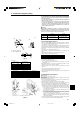
1. Safety precautions 1.3. Before electric work Caution: • Be sure to install circuit breakers. If not installed, electric shock may result. • For the power lines, use standard cables of sufficient capacity. Otherwise, a short circuit, overheating, or fire may result. • When installing the power lines, do not apply tension to the cables. If the connections are loosened, the cables can snap or break and overheating or fire may result. • Be sure to ground the unit.
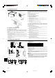
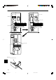
2. Installation location 2.4.2. When installing a single outdoor unit (Refer to the last page) A Minimum dimensions are as follows, except for Max., meaning Maximum dimensions, indicated. The figures in parentheses are for A42 models. Refer to the figures for each case. 1 Obstacles at rear only (Fig. 2-6) 2 Obstacles at rear and above only (Fig. 2-7) 3 Obstacles at rear and sides only (Fig. 2-8) ∗ 350mm, 13-25/32 inch for A12, A18 Fig. 2-3 4 Obstacles at front only (Fig.
4. Installing the refrigerant piping 4.1. Precautions for devices that use R410A refrigerant • Refer to page 3 for precautions not included below on using air conditioners with R410A refrigerant. • Use ester oil, ether oil, alkylbenzene oil (small amount) as the refrigeration oil applied to the flared sections. • Use C1220 copper phosphorus, for copper and copper alloy seamless pipes, to connect the refrigerant pipes. Use refrigerant pipes with the thicknesses specified in the table to the below.
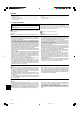
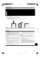
4. Installing the refrigerant piping A 4.4. Refrigerant pipe airtight testing method B A C (1) Connect the testing tools. • Make sure the stop valves A B are closed and do not open them. • Add pressure to the refrigerant lines through the service port C of the liquid stop valve D. (2) Do not add pressure to the specified pressure all at once; add pressure little by little. 1 Pressurize to 0.5 MPa (5 kgf/cm2G), wait five minutes, and make sure the pressure does not decrease. 2 Pressurize to 1.
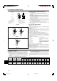
4. Installing the refrigerant piping 4.7. For twin/triple combination C A B A C D Refrigerant piping limitation of length, height difference are shown in the figure. (Fig. 4-7) A A B C D E E Indoor unit Outdoor unit Multi distribution pipe (option) Height difference (Indoor unit-Outdoor unit) Max. 30 m, 100 ft Height difference (Indoor unit-Indoor unit) Max. 1 m, 3 ft D A B B–C B–D C–D A12, A18 : A+B+C ≤ 30 m, 100 ft A24-A42 : A+B+C(+D) ≤ 50 m, 165 ft ≤ 8 m, 26 ft Fig. 4-7 5.
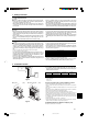
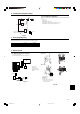
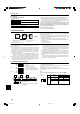
■ A12, A18 CORD COVER L1 L2 GR S1 S2 S3 TERMINAL BED CONDUIT COVER CABLE STRAP SERVICE PANEL ■ A24–42 CONDUIT PLATE : accessory 8 BG79U896H01_en 8 05.12.
6. Electrical work 6.2. Field electrical wiring Circuit rating Wiring Wire No. × size Outdoor unit model A12 A18 A24 A30 A36 A42 Outdoor unit power supply Single, 208/230 V, 60 Hz Single, 208/230 V, 60 Hz Single, 208/230 V, 60 Hz Single, 208/230 V, 60 Hz Single, 208/230 V, 60 Hz Single, 208/230 V, 60 Hz Breaker size 15A 15A 25A 30A 30A 30A Minimum circuit ampacity 13A 13A 18A 25A 25A 26A Maximum rating of overcurrent protective device 15A 20A 30A 40A 40A 40A Outdoor unit power supply 2 × Min.
7. Test run 7.2. Test run • After power is supplied, a small clicking noise may be heard from the inside of the outdoor unit. The electronic expansion valve is opening and closing. The unit is not faulty. • A few seconds after the compressor starts, a clanging noise may be heard from the inside of the outdoor unit. The noise is coming from the check valve due to the small difference in pressure in the pipes. The unit is not faulty.
6 inch 1/1 9-1 1 ax. 39-3/8 M ) 32 9/ 6 /1 5 -1 2 ( 5- 6) 3/1 1 1- 3 Fig. 2-6 7/8 (1 7- Fig. 2-7 /16 -11 . 19 x Ma 3-1 5/1 /8 ) ) 3/8 1 1- 3-1 5/1 7/8 6( 7-7 (1 6 /1 -11 7- /8 ) ) /32 -29 6) 3/1 3 /8) ( 39 6 /1 -11 9/3 2 (9 -27 /32 ) -3 (39 5-2 11-13/16 (19-11/16) 9/3 2 (9 -27 19 Fig. 2-9 /32 ) Fig. 2-10 Fig. 2-11 6 3/1 1-1 1 ax. M 39 5-2 -15 19 Fig.
3400 Lawrenceville Suwanee Road ● Suwanee, Georgia 30024 Toll Free: 800-433-4822 ● Toll Free Fax: 800-889-9904 www.mrslim.com Specifications are subject to change without notice.