
Installation manual

10
7. Test run
7.2. Test run
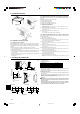
7.2.1. Using SW4 in outdoor unit
1) PUH Type, PUZ Type
SW4-1 ON
Cooling operation
SW4-2 OFF
SW4-1 ON
Heating operation
SW4-2 ON
2) PUY Type
SW4-1 ON
Cooling operation
SW4-2 ON or OFF
* After performing the test run, set SW4-1 to OFF.
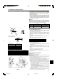
• After power is supplied, a small clicking noise may be heard from the inside of the outdoor
unit. The electronic expansion valve is opening and closing. The unit is not faulty.
• A few seconds after the compressor starts, a clanging noise may be heard from the
inside of the outdoor unit. The noise is coming from the check valve due to the small
difference in pressure in the pipes. The unit is not faulty.
The test run operation mode cannot be changed by DIP switch SW4-2 during
the test run. (To change the test run operation mode during the test run, stop
the test run by DIP switch SW4-1. After changing the test run operation mode,
resume the test run by switch SW4-1.)
7.2.2. Using remote controller
Refer to the indoor unit installation manual.
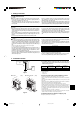
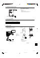
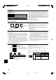
9. System control (Fig. 9-1)
* Set the refrigerant address using the DIP switch of the outdoor unit.
1 Wiring from the Remote Control
This wire is connected to TB5 (terminal board for remote controller) of the indoor unit
(non-polar).
2 When a Different Refrigerant System Grouping is Used.
Up to 16 refrigerant systems can be controlled as one group using the slim MA re-
mote controller.
Note:
In single refrigerant system (twin/triple), there is no need of wiring
22
22
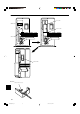
2.
Operation according to switch setting
ON OFF
Start Normal
Clear Normal
Settings for outdoor unit ad-
dresses 0 to 15
SW1
Function table
<SW1>
Function
1 Compulsory de-
frosting
2 Error history clear
3
4
5
6
ON
123456
OFF
A Outdoor unit
B Indoor unit
C Master remote controller
D Subordinate remote controller
E Standard 1:1 (Refrigerant address = 00)
F Simultaneous twin (Refrigerant address = 01)
G Simultaneous triple (Refrigerant address = 02)
TB4
TB5
TB1
TB4
TB5
TB4
TB1
TB4
TB1
TB4TB4
TB5
1
1
2
2
AA
BBBBBB
CD
AFGE
ON
OFF
3456
E SW 1 - 3 ~ 6
ON
OFF
3456
F SW 1 - 3 ~ 6
ON
OFF
3456
G SW 1 - 3 ~ 6
SW1
function
settings
Fig. 9-1
Refrigerant sys-
tem address set-
ting
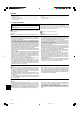
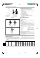
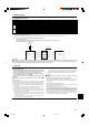
8.1. Low noise mode (on-site modification) (Fig. 8-1)
By performing the following modification, operation noise of the outdoor unit can be
reduced by about 3-4 dB.
The low noise mode will be activated when a commercially available timer or the
contact input of an ON/OFF switch is added to the CNDM connector (option) on the
control board of the outdoor unit.
• The ability varies according to the outdoor temperature and conditions, etc.
1 Complete the circuit as shown when using the external input adapter (PAC-
SC36NA). (Option)
2 SW1 ON: Low noise mode
SW1 OFF: Normal operation
8.2. Refrigerant collecting (pump down)
Perform the following procedures to collect the refrigerant when moving the indoor
unit or the outdoor unit.
1 Before collecting the refrigerant, first make sure that the all of the SW5 DIP switches
for function changes on the control board of the outdoor unit are set to OFF. If all of the
SW5 switches are not set to OFF, record the settings and then set all of the switches
to OFF. Start collecting the refrigerant. After moving the unit to a new location and
completing the test run, set the SW5 switches to the previously recorded settings.
2 Supply power (circuit breaker).
* When power is supplied, make sure that “CENTRALLY CONTROLLED” is not
displayed on the remote controller. If “CENTRALLY CONTROLLED” is dis-
played, the refrigerant collecting (pump down) cannot be completed normally.
3 After the gas stop valve is closed, set the SWP switch on the control board of the
outdoor unit to ON. The compressor (outdoor unit) and ventilators (indoor and
outdoor units) start operating and refrigerant collecting operation begins. LED1
and LED2 on the control board of the outdoor unit are lit.
* Only set the SWP switch (push-button type) to ON if the unit is stopped. How-
ever, even if the unit is stopped and the SWP switch is set to ON less than
three minutes after the compressor stops, the refrigerant collecting operation
cannot be performed. Wait until compressor has been stopped for three min-
utes and then set the SWP switch to ON again.
4 Because the unit automatically stops in about two to three minutes after the refrig-
erant collecting operation (LED1 and LED2 are lit), be sure to quickly close the
gas stop valve. When LED1 and LED2 are lit and the outdoor unit is stopped, open
the liquid stop valve completely, and then repeat step 3 after three minutes have
passed.
* If the refrigerant collecting operation has been completed normally (LED1 and
LED2 are lit), the unit will remain stopped until the power supply is turned off.
5 Turn off the power supply (circuit breaker).
A Circuit diagram example (low noise mode)
B On-site arrangement
C External input adapter (PAC-SC36NA)
SW1
CNDM
Red
Brown
Orange
BCD
E
3
1
D Outdoor unit control board
E Max. 10 m, 33 ft
Fig. 8-1
A
8. Special Functions
BG79U896H01_en 05.12.20, 11:03 AM10