
Installation manual

7
4. Installing the refrigerant piping
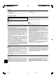
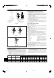
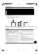
4.7. For twin/triple combination
Refrigerant piping limitation of length, height difference are shown in the figure. (Fig.
4-7)
A Indoor unit
B Outdoor unit
C Multi distribution pipe (option)
D Height difference (Indoor unit-Outdoor unit) Max. 30 m, 100 ft
E Height difference (Indoor unit-Indoor unit) Max. 1 m, 3 ft
A
A
A
C
E
D
DB
C
A
B
B–C
B–D
≤
8 m, 26 ft
C–D
A12, A18 : A+B+C
≤
30 m, 100 ft
A24-A42
: A+B+C(+D)
≤
50 m, 165 ft
Fig. 4-7
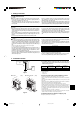
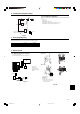
5. Drainage piping work
Outdoor unit drainage pipe connection
When drain piping is necessary, use the drain socket or the drain pan (option).
A12, A18 A24-A42
Drain socket PAC-SG61DS-E
Drain pan PAC-SG63DP-E PAC-SG64DP-E
A
B
C
D
E
Fig. 6-1
Fig. 6-2
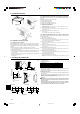
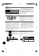
■ A24-A42
■ A12, A18
A Earth terminal
B Terminal block
C Clamp
D Service panel
E Wire the cables so that they do not
contact the center of the service
panel or the gas valve.
6.1. Outdoor unit (Fig. 6-1, Fig. 6-2)
1 Remove the service panel.
2 Wire the cables referring to the Fig. 6-1 and the Fig. 6-2.
A
C
B
S3
S3
S2
S1
S2S1L1 L2
GR
D
E
E
D
E
C
B
A A
E E
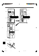
A Indoor unit
B Outdoor unit
C Remote controller
D Main switch (Breaker)
E Earth
For Power
For Power
L1
GR
L2 S1 S2 S3
E
B
A
F
C
L1
GR
L2 S1 S2 S3
6. Electrical work
BG79U896H01_en 05.12.20, 11:03 AM7