MOTION CONTROLLERS What is the newest in a motion wave ? Mitsubishi Electric Corporation Nagoya Works is a factory certified for ISO14001 (standards for environmental management systems) and ISO9001(standards for quality assurance managememt systems)
Introducing the Motion Controller Q Series, meeting the needs for higher performance and smaller size to satisfy high-speed motion control applications! Compatible with the Q Series PLC (Platform), which incorporates Multiple CPU technology, the Motion CPU and PLC CPU are selectable and work in parallel to provide greater flexibility and unmatched performance. A large-scale control system (Up to 96 axes per system) can be created using an extremely compact package as Q Series PLC.
CONTENTS Main Features ........................................................... 1 System Configuration ................................................ 3 Products Line-up ....................................................... 5 Multiple CPU System ................................................ 7 Motion SFC Program ................................................. 9 SV13 (Conveyor Assenmbly Use)................................. 19 SV22 (Automatic Machinery Use) .................................
System Configuration Flexible High-Speed Motion Control System Achieved with Multiple CPU. ■ Compatible with the Q Series PLC (Platform) in the Multiple CPU system. ■ The appropriate CPU modules for PLC control and motion control can be selected to meet the application reguirements. ■ The Multiple CPU configuration allows up to 4 CPU modules to be selected. (1 PLC CPU must be used.) ■ Up to 96 axes of servomotors per system can be controlled by using 3 modules of Q173CPUN.
■Operating system software line-up OS software(FD) SW6RN-SV Q Conveyor Assembly Use Automatic Machinery Use Motion SFC Motion SFC Provides constant-speed control, speed control, 1 to 4axes linear interpolation and 2-axes circular interpolation, etc. Ideal for use in conveyors and assembly machines.
Product-Line-up Motion CPU module Q173CPUN (Up to 32 axes control) Items Specifications Number of control axes Up to 32 axes 0.88ms : 1 to 8 axes 1.77ms : 9 to 16 axes SV13 3.55ms : 17 to 32 axes Operation cycle 0.88ms : 1 to 4 axes (default) 1.77ms : 5 to 12 axes SV22 3.55ms : 13 to 24 axes 7.
Servo external signals interface module Q172LX Items Upper stroke limit input, Lower stroke limit input, Stop signal input, Proximity dog/ speed-position switching input Number of input points Input method Rated input voltage/current Operating voltage range ON voltage/current OFF voltage/current Upper/lower stroke limit and Response STOP signal time Proximity dog/ speed-position switching signal Number of I/O occupying points 5VDC current consumption [A] Exterior dimensions [mm(inch)] Weight [kg] Spec
Multiple CPU System An Innovative Multiple CPU System Providing Advanced Performance and Control. Distribution of control processing ■ By distributing such tasks as machine control, communication control, servo control, and information control among multiple processors, CPU load is dramatically reduced, allowing extremely fast and efficient processing of complex applications. ■ Various I/O modules are assigned to their respective CPU module and can be used on the same base unit simultaneously.
Communication between the Motion CPU and PLC CPU ■ The optimum functions for your application needs are provided to exchange data between CPU modules. Communication method Automatic refresh Communication processing timing Scan processing Data amount Several hundred words to several kilo words Function Data exchange (Area-fixed) (Parameter-fixed) Application PLC CPU (CPU No.1) Motion CPU (CPU No.
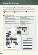
Motion SFC Program Powerful Programming Environment with Event Processing. ■ The Motion control program is described in flowchart form using the Motion SFC (Sequential Function Chart) format. By describing the Motion CPU program using the suitable Motion SFC function blocks, the Motion CPU can control the machine operation and aid in the event processing.
Multiple CPU control using PLC CPU and Motion CPU PLC CPU Motion CPU Device memory Device memory Shared memory Shared memory By distributing such tasks as servo control, machine control, and information control among multiple processors, the flexible system configuration can be realized. The program of Motion CPU is described in the Motion SFC program. Event processing The high-speed response (control for the signal output, servomotor start, speed change, etc.
Motion SFC Program Motion SFC operation PLC program (Note) Motion SFC program All steps are executed with constant scanning. Only active steps are executed following transition conditions.
Task operation examples of Motion SFC program Normal task Program 1 Program 2 • Normal task • Do not start automatically F20 F30 F1 F5 F2 F6 F3 F7 END F8 • Normal task • Do not start automatically END S(P).SFCS (Program 1 start) S(P).
Motion SFC Program Various programming tools in a effective background on Windows Integrated start-up support software MT Developer Servo data setting System design System setting ■ Set the servo parameter or fixed parameter, etc.
Integrated start-up support software MT Developer Function • Installation of operating system (OS) • Comparison of operating system (OS) • New creation, setting and reading of projects • Batch management of user files in project units • Setting of system configuration (Motion module, servo amplifier or servomotor, etc.) • Setting of high-speed reading data • Setting of servo parameters or fixed parameters, etc.
Motion SFC Program Motion SFC high-speed response control High-speed response to external inputs PLC program (A172SHCPUN) X10 Motion SFC program (Q173CPUN) [G100] SET PY0 = PX10 M100 Y0 PLC scan time 20ms OFF X10 (Input) PX10 (Input) ON OFF Y0 (Output) PY0 (Output) I/O output ■ The response time of output signal for the input signal from an external source is measured in this program. ■ The response time and dispersion affected by the scan time are approx. 20ms in the PLC program of A172SHCPUN.
Motion SFC specifications Motion SFC chart symbols Class Name Symbol START Program start/end Step Program name Function Indicates the program start (entrance) . END END Indicates the program end (exit) . Motion control step K Starts the servo program Kn. (Refer to page 20 for the servo instructions.) Once execution type operation control step F Executes the operation control program Fn once.
Motion SFC Program Example of Motion SFC program ■ This is a control example of assortment equipment which judges 3 types work and performs assortment conveyance on 3 lines.
Sub Motion SFC program Automatic operation program (Not automatic start) Automatic operation • Subroutin end with PX6 OFF [G10] PX7 //Automatic start ON? [G20] !PX6 //Switch to manual operation mode? P0 END • Positioning to b-point (Waiting point) [K150:Real] 1 ABS-1 Axis 1, 400000.0µm Speed 10000.
SV13 (Conveyor Assembly Use) Simple Programming Using Dedicated Instructions. ■ Colorful positioning controls and locus controls such as “1 to 4 axes linear interpolation, 2 axes circular interpolation, helical interpolation, positioning control, speed control or constant-speed control” are supported. Particularly simple programming for positioning systems is attained by using dedicated servo and PLC instructions. A variety of enhanced functions allow easy programming of conventionally complex systems.
Servo instructions Absolute 3-axes linear interpolation ABH Absolute radius-specified helical interpolation less than CCW 180˚ INC-3 Incremental 3-axes linear interpolation ABH Absolute radius-specified helical interpolation CCW 180˚ or more ABS-4 Absolute 4-axes linear interpolation INH Incremental radius-specified helical interpolation less than CW 180˚ INC-4 Incremental 4-axes linear interpolation INH Incremental radius-specified helical interpolation CW 180˚ or more INH Incremental radi
SV13 (Conveyor Assembly Use) Application examples X-Y table Sealing • Constant-speed locus control • Linear, circular interpolation • High speed, high-precision locus operation • 2-axes linear interpolation • 3-axes linear interpolation • 2-axes circular interpolation • Constant-speed locus control Z-axis r1 r2 X-axis Z X Y-axis Y Drilling machine Fixed-pitch hole drilling • Speed-switching control • Speed/position switching control Servomotor Position sensor 1st speed Speed control 2nd speed
Functions Skip function High speed reading function Positioning to the next positioning point by invalidating the positioning point during constant-speed control. Up to 11 data among 16 types (feed current value, deviation counter value, etc.) can be read simultaneously to the specified device using a signal from input module as a trigger. Uses : Handling positioning, etc.
SV22 (Automatic Machinery Use) Easy On-Screen Programming Using the Mechanical Support Language. ■ Incorporating a mechanical support language that allows easy programming of the mechanical system. By combining a variety of software mechanical modules and Cam patterns, complex synchronized control and coordinated control can be achieved easily and at low costs. Ideal for controlling automatic machinery such as food processing and packaging.
Mechanical support language Realizing mechanical operation using software Easy programming on screen using a mouse By replacing the mechanical system of main shafts, gears, clutches, and Cams with the software mechanical modules, the following merits can be realized. Machine is more compact and costs are lower. There are no worries over friction and service life for the main shaft, gear and clutch. Changing initial setup is simple.
SV22 (Automatic Machinery Use) Application examples Filling machine Filling Nozzle raised and lowered Conveyance Nozzle Filling Draw control V V+Draw Press conveyance Press machine Main press motor Die Import conveyor Synchronous encoder Export conveyor Work Work X-axis servomotor Y-axis servomotor Three dimensional transfer Lift (2) Lift AC servomotor Lift (1) Lift AC servomotor Feed Feed AC servomotor Clamp (2) Clamp AC servomotor Clamp (1) 25
Printing machine Mark detection function Synchronous operation between axes Tandem operation Torque control Printing part Processing part (Note) : Consult individually about the case applied to a printing machine. (It is necessary to use the operating system software, servo amplifiers and servomotors with special specification according to the system.) Synchronous control The servomotor can be operated by making it synchronous with other motor control conditions.
Overview of CPU Performance Motion control Item Q173CPUN Q172CPUN 32 axes 8 axes SV13 0.88ms : 1 to 8 axes 1.77ms : 9 to 16 axes 3.55ms : 17 to 32 axes 0.88ms : 1 to 8 axes SV22 0.88ms : 1 to 4 axes 1.77ms : 5 to 12 axes 3.55ms : 13 to 24 axes 7.11ms : 25 to 32 axes 0.88ms : 1 to 4 axes 1.
Mechanical system program (SV22) Item Drive module Control unit Output module Drive module Virtual axis Mechanical system program Transmission module Q173CPUN Virtual servomotor Synchronous encoder Roller Ball screw Rotary table Cam Virtual servomotor Synchronous encoder Virtual main shaft Virtual auxiliary input axis Gear (Note-1) Clutch (Note-1) Speed change gear (Note-1) Differential gear (Note-1) PLS mm, inch 32 12 32 32 Output module Cam Total 44 Total 64 Fixed as “degree” mm, inch, PLS 8 8 8
Overview of CPU Performance Software packages Software Operating system software Programming software Model name Q173CPUN Q172CPUN Application Conveyor assembly use SV13 Automatic machinery use SV22 Conveyor assembly use SV13 Automatic machinery use SV22 Digital oscilloscope use Note SW6RN-SV13QB SW6RN-SV13QD SW6RN-SV22QA SW6RN-SV22QC SW6RN-GSV13P SW6RN-GSV22P SW3RN-CAMP SW6RN-DOSCP – Included in the "Integrated start-up support software".
SSCNET connecting methods With Dividing unit MODE RUN ERR USER BAT BOOT POWER Without Dividing unit/External unit MODE RUN ERR USER BAT BOOT MODE RUN ERR USER BAT BOOT POWER MODE RUN ERR USER BAT BOOT Q173CPUN PULL Q173CPUN PULL PULL USB USB RS-232 RS-232 PULL PULL USB USB RS-232 RS-232 PULL SSCNET LINE 1 SSCNET LINE 1 CN1 CN1 Q 1 7 3 C P U N Dividing unit (Note-1) (Q173DV) CN1A CN1B Amplifier CN1A CN1B CN1A Amplifier Amplifier SSCNET LINE 2 CN1A CN1B Amplifier CN1A C
Combinations of Servo Amplifier and Servomotor (As of Apr. 2003) MR-J2M series MR-J2M- Servo amplifier 10DU Servomotor MR-J2-Super series 20DU 40DU Motor capacity (kW) MR-J2S70DU 10B 20B 40B 60B 70B 100B 200B 350B 500B 700B HC-MFS053 Ultra low inertia, Small capacity HC-MFS13 HC-MFS HC-MFS23 3000r/min HC-MFS43 series HC-MFS73 0.05 HC-KFS053 Low inertia, Small capacity HC-KFS13 HC-KFS HC-KFS23 3000r/min HC-KFS43 series HC-KFS73 0.
(As of Apr. 2003) MR-J2-Super series 500B Servomotor 700B 11KB 15KB 22KB 30KB HA-LFS601 37KB4 45KB4 55KB4 8.0 12.0 HA-LFS15K1 15.0 HA-LFS20K1 20.0 HA-LFS25K1 25.0 HA-LFS30K1 30.0 HA-LFS37K1 37.0 HA-LFS30K14 30.0 HA-LFS37K14 37.0 7.0 HA-LFS11K1M 11.0 HA-LFS15K1M 15.0 HA-LFS22K1M 22.0 HA-LFS30K1M 30.0 HA-LFS37K1M 37.0 HA-LFS30K1M4 30.0 HA-LFS37K1M4 37.0 HA-LFS45K1M4 45.0 HA-LFS50K1M4 50.0 HA-LFS502 5.
Exterior Dimensions CPU module Q173CPUN CPU module Q172CPUN MODE RUN ERR. M.RUN BAT. BOOT MODE RUN ERR. M.RUN BAT. BOOT CN1 98(3.86) CN2 PULL FRONT SSCNET 98(3.86) FRONT SSCNET CN2 PULL CN1 USB USB RS-232 RS-232 4.5(0.18) 4.5(0.18) 27.4(1.08) 27.4(1.08) 114.3(4.50) 114.3(4.50) [Unit : mm (inch)] [Unit : mm (inch)] Servo external signals interface module Q172LX Serial absolute synchronous encoder interface module Q172EX CTRL 98(3.86) 98(3.86) SY.ENC1 SY.ENC2 Q172EX Q172LX 27.
φ15(0.59) -0.006 -0.017 B Specifications Resolution 16384PLS/rev Direction on increase Counter clockwise (viewed from end of axis) Protective construction IP52 φ50(1.97)-0.009 -0.025 φ68(2.68) Item 56(2.2) 56(2.2) N.P B 68(2.68) 68(2.68) 0 φ14.3(0.56)-0.11 0 φ14.3(0.56)-0.11 φ16(0.63) φ67(2.64) Serial absolute synchronous encoder MR-HENC Permitted axis load Radial : Up to 98N Thrust : Up to 49N Permissible rotation speed 4300r/min Permissible angular acceleration 40000rad/s2 1.15(0.
For safe use • To use the products given in this catalog properly, always read the “manuals” before starting to use them. • This product has been manufactured as a general-purpose part for general industries, and has not been designed or manufactured to be incorporated in a device or system used in purposes related to human life. • Before using the product for special purposes such as nuclear power, electric power, aerospace, medicine or passenger movement vehicles, consult with Mitsubishi.