
Specifications


Multiple CPU System
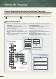
An Innovative Multiple CPU System Providing Advanced Performance and Control.
Open field network
(CC-Link)
Motion CPU
• Servo control
• Event control
• Usable also as the PC
CPU monitor
PC CPU
void monitor(void){
int isHot = 0;
int isNot = 0;
isNot = 1;
while(runState ==
:
• Data control
• Data collection
• Higher rank
communication
Motion CPU
control modules
SSCNET
Higher rank
network
PLC CPU
•
Sequence control
• Communication
control
PLC CPU
control modules
Temperature control module
Electrically operated value
Printer
Distribution of control processing
Flexible Multiple CPU system configuration
Host computer
7
3.55
1.77
0.88
1 to 8 9 to 16 17 to 32
[ms]
The motion operation cycle can
be selected in the Motion CPU.
Priority is given to the number
of axes or operation cycle
(specifications) to select the
CPU configuration.
1
1
2
3
32
64
96
23
Number of PLC CPU modules
POWER
PULL
MODE
RUN
ERR
USER
BAT
BOOT
USB
RS-232
PULL PULL
USB
RS-232
MODE
RUN
ERR
USER
BAT
BOOT
MODE
RUN
ERR
USER
BAT
BOOT
USB
RS-232
PULL PULL
USB
RS-232
MODE
RUN
ERR
USER
BAT
BOOT
(Note-1)
Qn(H)
CPU
Qn(H)
CPU
POWER
PULL
MODE
RUN
ERR
USER
BAT
BOOT
USB
RS-232
PULL PULL
USB
RS-232
MODE
RUN
ERR
USER
BAT
BOOT
MODE
RUN
ERR
USER
BAT
BOOT
USB
RS-232
PULL
POWER
PULL
MODE
RUN
ERR
USER
BAT
BOOT
USB
RS-232
PULL PULL
USB
RS-232
MODE
RUN
ERR
USER
BAT
BOOT
MODE
RUN
ERR
USER
BAT
BOOT
USB
RS-232
PULL PULL
USB
RS-232
MODE
RUN
ERR
USER
BAT
BOOT
(Note-2)
Qn(H)
CPU
Qn(H)
CPU
Qn(H)
CPU
Qn(H)
CPU
Qn(H)
CPU
POWER
PULL
MODE
RUN
ERR
USER
BAT
BOOT
USB
RS-232
PULL PULL
USB
RS-232
MODE
RUN
ERR
USER
BAT
BOOT
POWER
PULL
MODE
RUN
ERR
USER
BAT
BOOT
USB
RS-232
PULL PULL
USB
RS-232
MODE
RUN
ERR
USER
BAT
BOOT
MODE
RUN
ERR
USER
BAT
BOOT
USB
RS-232
PULL PULL
USB
RS-232
MODE
RUN
ERR
USER
BAT
BOOT
POWER
PULL
MODE
RUN
ERR
USER
BAT
BOOT
USB
RS-232
PULL PULL
USB
RS-232
MODE
RUN
ERR
USER
BAT
BOOT
MODE
RUN
ERR
USER
BAT
BOOT
USB
RS-232
PULL
(Note-2) (Note-2)
Qn(H)
CPU
Qn(H)
CPU
Qn(H)
CPU
Number of control axes
GOT
• Data setting
• Monitor
By distributing such tasks as machine control, communication control, servo control, and information control among multiple processors,
CPU load is dramatically reduced, allowing extremely fast and efficient processing of complex applications.
Various I/O modules are assigned to their respective CPU module and can be used on the same base unit simultaneously.
■
■
Multiple CPU configuration allows up to 4 CPU modules to be selected for the systems and control axes.
■
Number of Motion CPU modules
Number of maximum control axes
Motion operation cycle(SV13 use/default)
PC
CPU
PC
CPU
PC
CPU
Be careful of a 5VDC power supply capacity. Select the Q64P (5VDC 8.5A) as required.
The PC CPU can be installed to the right-hand side of Motion CPU.
(Note-1) :
(Note-2) :
Q173
Q172
CPU
Q173
Q172
CPU
Q173
Q172
CPU
Q173
Q172
CPU
Q173
Q172
CPU
Q173
Q172
CPU
Q173
Q172
CPU
Q173
Q172
CPU
Q173
Q172
CPU
Q173
Q172
CPU