
Instruction manual


2 - 83
2 SYSTEM CONFIGURATION
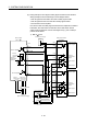
(4) Wiring example for the safety signal module
(a) Wiring example for door signal to safety signal module and AC contactor.
Wiring example to shut off contactor by the followings is shown diagram
below.
• Shut-off signal from the Motion CPU side of safety signal module
• Shut-off signal from the PLC CPU side of safety signal module
• Contactor shut-off output MC1 and MC2 of servo amplifier
Input the output signal of auxiliary normally closed contact into the safety
signal module to detect the weld of contactor.
Door sensor used as a safety signal should have two outputs and is wired to
both Motion CPU side and PLC CPU side. Sensor and switch used as
safety signal should be the ones for weak signal use (e.g. twin contact) to
prevent contact failure.
Door1 close/open
confirmation sensor
24VDC
External power supply
(Main circuit power supply)
L1 L2 L3
Servo amplifier
(MR-J3- B)
Reactor
MC2 normally
closed signal
Door1 signal
Door2 signal
Motion IO
1B01
1B09
1A19
1A18
1A17
1A01
PLC IO
2B01
2B09
2A19
2A18
2A17
2A01
Motion CPU side
Drive power
shut-off signal
PLC CPU side
Safety signal module
(Q173DSXY)
MC1 normally
closed signal
1A20
2A20
Main circuit
power supply
L1 L2 L3
Control
power supply
L11 L21
MC1
MC2
Relay
Contactor
#1
Relay
Contactor
#2
: Wiring for assist the safety signal
: Wiring for input/output control
of the safety signal
MC2 normally
closed signal
Door1 signal
Door2 signal
Drive power
shut-off signal
MC1 normally
closed signal
Door2 close/open
confirmation sensor