
Instruction manual


4 - 2
4 INSTALLATION AND WIRING
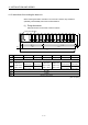
(3) Tighten the module fixing screws and terminal block screws within the tightening
torque range specified below.
Location of screw Tightening torque range [N•m]
Motion CPU module fixing screw (M3 13 screw) 0.36 to 0.48
Module fixing screw (M3 12 screw) 0.36 to 0.48
I/O module terminal block screw (M3 screw) 0.42 to 0.58
I/O module terminal block fixing screw (M3.5 screw) 0.68 to 0.92
Power supply module terminal screw (M3.5 screw) 0.68 to 0.92
(4) Be sure to install a power supply module on the main base unit and extension
base unit. Even if the power supply module is not installed, when the I/O modules
and intelligent function module installed on the base units are light load type, the
modules may be operated. In this case, because a voltage becomes unstable, we
cannot guarantee the operation.
(5) When using an extension cable, keep it away from the main circuit cable (high
voltage and large current).
Keep a distance of 100mm (3.94inch) or more from the main circuit.
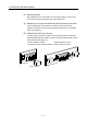
(6) Be sure to fix a main base unit to the panel using mounting screws. Not doing so
could result in vibration that may cause erroneous operation.
Mount a main base unit in the following procedure.
(a) Fit the two base unit top mounting screws into the enclosure.
Panel
(b) Place the right-hand side notch of the base unit onto the right-hand side
screw.
Panel