
Specifications


3 - 13
3 COMMON PARAMETERS
(3) External signal input
Servo external signal (Upper stroke limit/Lower stroke limit/Stop signal/Proximity
DOG) can be selected for every axis from the following two methods.
(a) Q172LX Servo external signals interface module use
Set the servo external signals interface module, and set axis No. as the
"External signal setting" in the system setting.
(b) Servo amplifier input device use (MR-J3-B use only)
Set "Amplifier input valid" as the external signal input setting in the "Amplifier
setting" of system setting.
There are following restrictions to use.
• Count type home position return cannot be used.
• Speed/position switching control cannot be executed.
• Stop signal (STOP) cannot be used.
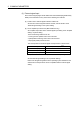
The correspondence of external signal and input device is shown below.
External signals
Input device (CN3)
(Note)
Upper stroke limit (FLS) DI1
Lower stroke limit (RLS) DI2
Proximity DOG (DOG) DI3
(Note): Refer to the "MR-J3-B Servo Amplifier Instruction Manual" for pin configurations.
Set the external signal setting in the "Input Filter Setting".
Refer to the Programming Manual of the operating system software for the
software and correspondence version compatible with the external signal
setting.