
Specifications


3 - 20
3 COMMON PARAMETERS
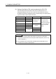
Table 3.1 Servo parameter (Basic setting parameters) list (Continued)
LED
display
Symbol Item Setting details
Setting value/setting range
(Setting by setup software)
Section
• Select the gain adjustment mode.
Name
Automatically set
parameter
0: Interpolation mode
PB06, PB08, PB09,
PB10
1: Auto tuning mode 1
PB06, PB07, PB08,
PB09, PB10
2: Auto tuning mode 2
PB07, PB08, PB09,
PB10
3: Manual mode
—
PA08 ATU Auto tuning mode
0: Interpolation mode
1: Auto tuning mode 1
2: Auto tuning mode 2
3: Manual mode
3.3.5
1 : Low response (10.0Hz)
2 : (11.3Hz)
3 : (12.7Hz)
4 : (14.3Hz)
5 : (16.1Hz)
6 : (18.1Hz)
7 : (20.4Hz)
8 : (23.0Hz)
9 : (25.9Hz)
10 : (29.2Hz)
11 : (32.9Hz)
12 : (37.0Hz)
13 : (41.7Hz)
14 : (47.0Hz)
15 :
(59.2Hz)
16 : Middle response (59.6Hz)
17 : (67.1Hz)
18 : (75.6Hz)
19 : (85.2Hz)
20 : (95.9Hz)
21 : (108.0Hz)
22 : (121.7Hz)
23 : (137.1Hz)
24 : (154.4Hz)
25 : (173.9Hz)
26 : (195.9Hz)
27 : (220.6Hz)
28 : (248.5Hz)
29 : (279.9Hz)
30 : (315.3Hz)
31 :
(355.1Hz)
PA09 RSP Auto tuning response
• Set to increase the response of servo
amplifier.
(At the automatic tuning valid.)
• Optimum response can be selected
according to the rigidity of machine.
• As machine rigidity is higher, faster response
can be set to improve tracking performance
in response to a command and to reduce
setting time.
32 : High response (400.0Hz)
3.3.6
PA10 INP In-position range
• Set the range which outputs the positioning
completion in the command pulse unit.
0 to 50000[PLS] 3.3.7
0: Forward rotation (CCW) with
positioning address increase
PA14 POL Rotation direction selection
• Set the rotation direction at load side of the
servomotor.
1: Reverse rotation (CW) with
positioning address increase
3.3.8