
Instruction manual


2 - 69
2 SYSTEM CONFIGURATION
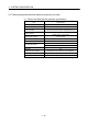
(3) Teaching unit specifications
Specifications
Items
A31TU-D3
A31TU-DN
Language Japanese
Tact switch 28 keys for SV
ENABLE/DISABLE switch Operation enable/disable
Emergency stop switch Push lock return reset type
Deadman switch 3-position switch None
Operation
Contrast adjusting switch Shade/light
Display method 4 lines × 16 characters LCD display
Interface Conforming RS-422
Protective construction IP54 equivalent
Ambient temperature 0 to 40°C (32 to 104°F)
5VDC power supply Supplied from Motion CPU
5VDC consumption current [A] 0.26
Mass [kg] 1.74 (Including cable 5m (16.40ft.))
POINTS
(1) The total extended distance of cable between the Motion CPU and teaching
unit is within [30m(98.43ft.)] including the A31TU-D3
/A31TU-DN cable
[5m(16.40ft.)]
(2) The teaching unit is shipped, a protection sheet is attached in the surface of
the display and operation key to prevent the crack for conveyance. Remove a
protection sheet to use. Operation and display check without removing a
protection sheet are possible, however adhesives may remain in a teaching
unit by secular change.
(3) When the servomotor is operated by the JOG feed, etc. using the teaching unit
(A31TU-D3
) with deadman switch, operate it pushing the deadman switch at
middle position. The emergency stop state of Motion CPU occurs by gripping
or releasing this switch, and the servomotor stops and becomes coasting
state.
(4) Connection between the teaching unit and Motion CPU
(a) Connection between the teaching unit (A31TU-D3 ) and
Motion CPU (Q173HCPU-T/Q172HCPU-T)
1) Connect the cable for teaching unit (Q170TUD3CBL3M) between the
TU connector of Motion CPU (Q173HCPU-T/Q172HCPU-T) and
control panel. (Refer to the exterior dimensions of "APPENDIX 1.3
Cable for the teaching unit" and "APPENDIX 2.7 Connector", when it is
fit to the control panel.)
2) Connect the connector for external safety circuit (connector for
emergency stop switch×2 sets, connector for deadman switch×2 sets
and connector for emergency stop input to Motion CPU×1 set) to the
external safety circuit.
3) Connect the teaching unit (A31TU-D3
) to the cable for teaching unit
(Q170TUD3CBL3M) connected to the control panel.