Air-Conditioners SUZ-KA25,KA50, KA60, KA71VA3 SUZ-KA35VA2 INSTALLATION MANUAL FOR INSTALLER For safe and correct use, read this manual and the indoor unit installation manual thoroughly before installing the air-conditioner unit.
Contents 1. 2. 3. 4. The following should always be observed for safety . . . . . . . . . . . . . . . . . . . . Selecting the installation location . . . . . . . . . . . . . . . . . . . . . . . . . . . . . . . . . . . Installation diagram . . . . . . . . . . . . . . . . . . . . . . . . . . . . . . . . . . . . . . . . . . . . . Drain piping for outdoor unit . . . . . . . . . . . . . . . . . . . . . . . . . . . . . . . . . . . . . . . 2 2 3 3 5. Refrigerant piping work . . . . . . . . . . . . . . . . .
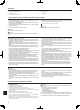
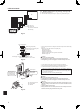
. Installation diagram 3.1. Outdoor unit (Fig. 3-1) SUZ-KA25VA3 SUZ-KA35VA2 Ventilation and service space ■ SUZ-KA25VA3, SUZ-KA35VA2 A 100 mm or more B 350 mm or more C Basically open 100 mm or more without any obstruction in front and on both sides of the unit. D 200 mm or more (Open two sides of left, right, or rear side.
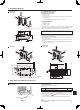
5. Refrigerant piping work 5.1. Refrigerant pipe (Fig. 5-1) (A) A Indoor unit B Outdoor unit ► Check that the difference between the heights of the indoor and outdoor units, the length of refrigerant pipe, and the number of bends in the pipe are within the limits shown below. Models SUZ-KA25/KA35 SUZ-KA50/KA60/KA71 (B) (A) Pipe length (one way) Max. 20 m Max. 30 m (B) Height (C) Number of difference bends (one way) Max. of 10 Max. 12 m Max. 30 m *(15 m) Max.
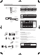
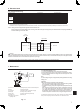
. Refrigerant piping work 5.2.5. Check (Fig. 5-7) / B • Compare the flared work with a figure in right side hand. • If flare is noted to be defective, cut off the flared section and do flaring work again. 0 2 3 4 5 6 1 7 Fig. 5-7 a Smooth all around b Inside is shining without any scratches c Even length all around d Too much e Tilted • Apply a thin coat of refrigeration oil on the seat surface of pipe. (Fig.
. Electrical work 6.1. Outdoor unit (Fig. 6-1, Fig. 6-2, Fig. 6-3, Fig. 6-4) S1 S2 S3 1 Remove the service panel. 2 Wire the cables referring to the Fig. 6-1, Fig. 6-2, Fig. 6-3 and the Fig. 6-4. 1 2 S1 S2 S3 L N A Indoor unit B Outdoor unit C Wired main switch/fuse D Grounding Fig. 6-1 For Power supply Indoor terminal block Earth wire (green/yellow) Indoor/outdoor unit connecting wire 3-core 1.
6. Electrical work 6.2. Field electrical wiring Circuit rating Wiring Wire No. × size (mm2) Outdoor unit model Outdoor unit power supply Outdoor unit input capacity Main switch (Breaker) Outdoor unit power supply *1 Outdoor unit power supply earth Indoor unit-Outdoor unit Indoor unit-Outdoor unit earth Outdoor unit L-N Indoor unit-Outdoor unit S1-S2 Indoor unit-Outdoor unit S2-S3 *2 *2 *2 SUZ-KA25/KA35 ~/N (single), 50 Hz, 230 V 10 A 2 × Min. 1.
Please be sure to put the contact address/telephone number on this manual before handing it to the customer. HEAD OFFICE: TOKYO BLDG.