SERVICE MANUAL FA9M068002 TRIUM 110 R E V I S I O N S +: (: FAX: V A: Création L. LUCE E R S I O N S 05/02 Rédigé par Vérifié par Approuvé par Written by Checked by Approuved by L. LUCE J. J. DEBEY G. LEBASTARD Mitsubishi Electric Telecom Europe S.A. After Sales Services Z.A.
Service Manual Trium 110 CONTENTS 1 General description 3 1.1 Description of the kit 3 1.2 Additional Accessories 4 2 Assembly 6 2.1 Exploded diagram of M6A 6 2.2 Spare part list 6 2.3 Disassembly and Assembly Instruction 7 2.3.1 Disassembly Instruction 2.3.2 Assembly Instruction 7 7 3 Download 7 3.1 Download of Software and settings 4 Basic Adjustment 7 9 4.1 Equipment installation 9 4.2 Basic Adjustment 10 4.2.1 Power Adjustment 4.2.2 RSSI control.
Service Manual Trium 110 8 Trouble Shooting help guide 12 9 Hardware description 14 9.1 Power management 14 9.1.1 Power Supply 9.1.2 Battery management 9.1.3 Power on/off 14 15 16 10 RF Section. 17 10.1 Frequency range. 17 10.1.1 E-GSM Frequency : 10.1.2 DCS Frequency : 17 17 10.2 Synthetiser Circuit Description. 18 10.3 RF Block Diagram. 19 10.4 Reception 19 10.4.1 Reception Block Diagram. 10.4.2 Description of Reception Block Diagram 10.5 Transmission. 20 10.5.
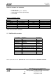
Service Manual Trium 110 1 General description M6A+ product is based on MARS product 1.1 Description of the kit Commercial Name TRIUM 110 Project Development Name - TRIUM 110 : Standard version - TRIUM110 m: For messaging, EMS version - TRIUM 110 p: For play, EXEN version CUPID MT 360 PICTURE Main features: Hand phone working with E-GSM/DCS networks Hand phone including a WAP Browser 1.2.
Service Manual Trium 110 4 items are included in the standard kit: • • • • Cupid main unit Li-Ion main battery (3.8V – 800mAh) AC/DC Adapter for battery rapid charging User manual Difference with MARS & M6A* Features Hardware Flash Memory Memory Back up battery Mechanical Handstrap LED indicator Cupid M6A* MARS Flash 2Mbytes Flash 2Mbytes No 4 Mbytes multi-bank None No 2 Mbytes EEPROM or Serial-Flash Yes Yes No Yes No No Yes * M6A: AURA, MYSTRAL, ODYSSEY 1.
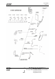
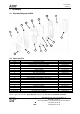
Service Manual Trium 110 FRONT PANEL MA 0640 COVER BATTERY MA0604 BATTERY MA 0632 MA0503 MA0504 MA0505 MA0502 MA0501 Simple Hand free MA0638 Professional MA0524 Enhanced MA0571 MA0514 MA0512 To be defined Standard MA0509 Head set With button To be defined MA0513 MA0605 NECK STRAP MA0606 HAND STRAP MA0607 Version A Date: 05/02 5/22 +: Mitsubishi Electric Telecom Europe S.A. After Sales Services Z.A.
Service Manual Trium 110 2 Assembly 2.1 Exploded diagram of M6A 15 16 12 7 6 5 2 1 17 14 11 8 3 2.
Service Manual Trium 110 2.3 Disassembly and Assembly Instruction 2.3.1 Disassembly Instruction The procedure for mobile disassembly is described in the instruction GFZ13136904 – TRIUM 110 Disassembly (M6A+ Cupid). 2.3.2 Assembly Instruction The procedure for mobile assembly is described in the instruction GFZ13136903 – TRIUM 110 Assembly (M6A+ Cupid). 3 Download The data are divided in two parts: the software and the settings. Currently the Mitsubishi software ( .
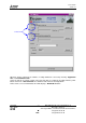
Service Manual Trium 110 Selection File When IPL Trium is launched, the software or setting download is selected by choosing “Application File”or “Personalization File” Select the .bin file or .psb file or both, connect the PC cable to a switched off mobile, hold the power button and click on “Start download”, the download starts when the back light blinks. At the end of a successful download, the mobile displays “Download success ”. Version A Date: 05/02 8/22 +: Mitsubishi Electric Telecom Europe S.
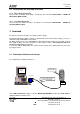
Service Manual Trium 110 4 Basic Adjustment For M6 family, test mode is not directly possible from the mobile, indeed relevant software is available on PC only. Thanks to the new generation of MT Tools (MT Tools 2000), we can either repair Level 2 or Level 3. 4.1 Equipment installation RADIOCOMMUNICATION TESTER Mobile without battery GPIB Connection for Autotest only (not requested for test mode) CORDON M5 RF SMA M/SMA M (F5CN000210) M5 RF CABLE SMA L100 (F5CN000310) External supply 4.
Service Manual Trium 110 4.2 Basic Adjustment Use MT Tools 2000 1(Vers.103 Ed.02 or higher) to set all the parameters. 4.2.1 Power Adjustment Each mobile is adjusted in the factory and the TX parameters (Power Control Level values and ramping values) are stored in the Flash Data (IC202) About the adjustment value of TX Power, see the following table.
Service Manual Trium 110 5 Block Diagram SIM Connector GSM Radio Module Keyboard Radio Interface IC300 ONE-C 1.2 BUS controller Code Flash LED Keyboard JTAG/DAI Data Flash I/ O GPIO PC cable UART 1 RAM Flux Control SPI bus External Audio LCD controller Micro 3 tones IC C o n n e c t o r IPD Charge r Li-Ion Battery Switches &Filters Amplifier Speaker LCD Display IPD Intergrate Power Device IC100 LED 2.8VD 2.8 ANA 2.8V AUD 2.5VD 2.5 ANA REG2 REG80 2.
Service Manual Trium 110 7 Repair Logigrams ( to be completed ) The repair logigrams are achieved after few mobile returns to the Mitsubishi’s after sales service. Then these logigrams are delivered in FI instructions form to the repair centers via E-mail.
Service Manual Trium 110 LOCATION UPDATE No service EGSM & DCS TX & RX good in test mode Soft updating No service EGSM & DCS After a soft updating still no good IC300 No training sequence Check VREF3, if parasite exist Change C155, check C101 No training sequence No modulation IC401 RX level no good With a –83db signal check the RSSI (= 27 ±4), RSSI good (10< <100) and the mobile lose the network RSSI no good, RSSI > 100 RX level no good RSSI no good, RSSI < 10 SW700 RX qual no good IC300
Service Manual Trium 110 9 Hardware description 9.1 Power management 9.1.1 Power Supply Initial conditions: C155 REG2 =2.8V R104 EXPS = 4.32V C150 2.8VANA =2.81V IC101 BBPWR = 2.49V TR100 D122 PWRKEY = 3.3V 2.5VD = 2.5V TR100 C159 3.6VB = 4.19V 2.8VD = 2.93V 8VAUD = 2.78V C108 TP113 2.8RTC = 3.28V C110 2.5RTC = 2.49V C104 Version A Date: 05/02 14/22 +: 2.8VANA = 2.49V Mitsubishi Electric Telecom Europe S.A. After Sales Services Z.A.
Service Manual Trium 110 9.1.2 Battery management 9.1.2.1 Block Diagram / Description Regarding the CUPID, the battery is Li-Ion 800 mAh, 3.8 V, whereas the external power supply is 5.7 V, 600 mA nominal. EXPS: AC/DC CLA HF kit When an external power supply is 2 plugged, the voltage of EXPS is 5.7 V, therefore battery does not supply anymore the Base Band (via IPD regulators). Indeed, the voltage from the EXPS is always greater than the one from battery, the diode D100 is no more opened. 5.
Service Manual Trium 110 3. Trickle mode: This phase is necessary to complete the charge and to avoid battery auto discharge. Charge current during this phase is 1 20 C. Trickle charge is automatically stopped after 24 hours duration. 9.1.3 Power on/off 9.1.3.1 Power on To switch on the mobile, three possibilities exist : With a battery : PWRKEY t BBPWR IC300 t MUPSU IC100 pin49 t During these mode TESTPS and EXPS = low voltage level.
Service Manual Trium 110 9.1.3.2 Power off. PWRKEY t 3s BBPWR MUPSU t 5s 10 RF Section. 10.1 Frequency range. 10.1.1 E-GSM Frequency : 124 Channels. 1≤ N ≤124 and 48 Channels. 975 ≤ N ≤1023 Receive frequency : 925.2~959.8 MHz RX frequency = 935.0+0.2*N for (1≤ N ≤124) and 935.0+0.2*(N-1024) for ( 975 ≤ N ≤1023) Transmit frequency : 880.2~914.8 MHz TX frequency = 890.0+0.2*N for (1≤ N ≤124) and 890.0+0.
Service Manual Trium 110 10.2 Synthetiser Circuit Description. IC401 CLK SDATA EN IF PLL RF PLL IC600 RF VCO RF DUAL BAND TCXO 13Mhz X600 OSW Switching between GSM and DCS band is performed by programming the IC401 with the serial data in BBE from CPU. The serial data lines are connected directly to the serial input pin of the RF IC (IC 401), and are used to program the 2 PLLs of the IC. The RF IC has two PLLs : one is variable frequency (RF PLL), and the other is fixed frequency (IF PLL).
Service Manual Trium 110 10.3 RF Block Diagram. AN Tn GSM RX 925-960Mhz FL400 LOW NOISE AMPLI IC400 FILTER J40 0 SW DCS RX 1805-1880Mhz FL402 FILTER FL401 FL403 BS FILTER + SWITCH DEMO RF VCO R/ X IC401 SW700 T/ X TCXO13MHz MOD DCS TX 1710- GSM TX 880- Z701 POWER AMPLI. ATT9dB COUPLEUR TX VCO Z700 IC701 ATT8dB IC700 LOOP FILTER GSM 424Mhz DCS 424Mhz APCCN COMP IC710 10.4 Reception 10.4.1 Reception Block Diagram.
Service Manual Trium 110 10.4.2 Description of Reception Block Diagram E-GSM band (925-960MHz). Incoming RF signal from aerial is filtered and switched to the RX GSM path through SW700 . The signal is filtered by FL400 , before to be amplified by IC400 , and is further filtered by FL402. Then, the RF signal (925-960 MHz) is mixed with a frequency (1150-1185 MHz) coming from the RF-PLL and controlled by the RF-VCO (IC602).
Service Manual Trium 110 DCS Band (1710-1785MHz). A phase locked loop is created around the TXVCO IC700. The output is fed into IC401 and converted to 424 MHz by mixing with RFVCO at 1286-1361 MHz. This 424 MHz signal is compared with the 424MHz signal from the modulators, and the error signal is used to control the TXVCO. Note that the error signal on the IC700 input will have a DC component to control frequency, and an AC component at approx 424 MHz to control phase changes.
Service Manual Trium 110 11 Personal Notes Mitsubishi Electric reserves the right to make changes to its products at any time to improve reliability or manufacturability. Mitsubishi Electric does not assume any liability arising from the use of any device or circuit described here in, nor does it convey any license under its patent rights or the rights of others. Version A Date: 05/02 22/22 +: Mitsubishi Electric Telecom Europe S.A. After Sales Services Z.A.