
Service manual
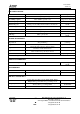

Service Manual
Trium 110
Version A
Date: 05/02
21/22
+:
(:
FAX:
Mitsubishi Electric Telecom Europe S.A.
After Sales Services
Z.A. Pigeon Blanc, 35 370 St Germain du Pinel France
+33 (0)2 23 55 16 30
+33 (0)2 99 75 71 62
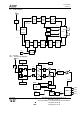
DCS Band (1710-1785MHz).
A phase locked loop is created around the TXVCO IC700. The output is fed into IC401 and converted to 424 MHz by mixing
with RFVCO at 1286-1361 MHz. This 424 MHz signal is compared with the 424MHz signal from the modulators, and the error
signal is used to control the TXVCO. Note that the error signal on the IC700 input will have a DC component to control
frequency, and an AC component at approx 424 MHz to control phase changes. Then the signal is filtered, attenuated by a filter
allowing an impedance adaptation with the power amplifier IC701. From the PA, the output goes through coupler Z 700, is
switched to the TX path and is filtered by SW700. The signal then goes up to the antenna.
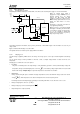
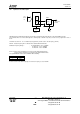
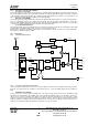
10.5.3 Power Control.
APCCNT is the reference waveform voltage for a TX burst (provided by IC300).
TX3SW-DCS : This control signal is used to switch on/off the DCS path through the TXVCO (IC700)
H.Level : The DCS part inside the TXVCO is active.
L.Level : The DCS part inside the TXVCO is not active.
TX3SW-GSM : This control signal is used to switch on/off the GSM path through the TXVCO (IC700)
H.Level : The GSM part inside the TXVCO is active.
L.Level : The GSM part inside the TXVCO is not active.
TX3SW :This control signal is used to switch on/off the operational amplifier of the APC Loop (IC710).
H. Level : Detecting Circuit and comparison Error AMP is active.
L. Level : Detecting Circuit and comparison Error AMP is not active.
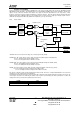
RF signal is rectified by voltage doubler Schottky barrier diodes D700. This level is compared with APCCNT. The result of the
comparison is used to vary the gain of the HPA IC701.
The APCCNT signal input from the base band circuit (IC300) contains the burst shaping information and the power level to be
set among the 15 power levels defined by the GSM, or the 16 power levels defined by the DCS specifications. It controls the
output power level by a feed-back loop (Automatic Power Control ).
E-GSM DCS
PCL 5 → +33 dBm PCL 0 → +30 dBm
PCL 19 → +5 dBm PCL15 → +0 dBm
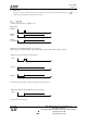
From TXVCO
DCS RF OUT
(IC700)
From TXVCO
GSM RF OUT
(IC700)
ATT 8dB
ATT 9dB
Directional
Coupler
(Z700)
Directional
Coupler
(Z701)
To Antenna
SW (SW700)
Detecting
Circuit
D700
-
APCCNT
TX3SW
TX3SW-DCS
Dual HPA (IC701)
Comparison
Error
AMP(IC710)
VAPC for
HPA
TX3SW-GSM
DCS
GSM
To Antenna
SW (SW700)